146 Set Up
Chapter Two: Installation
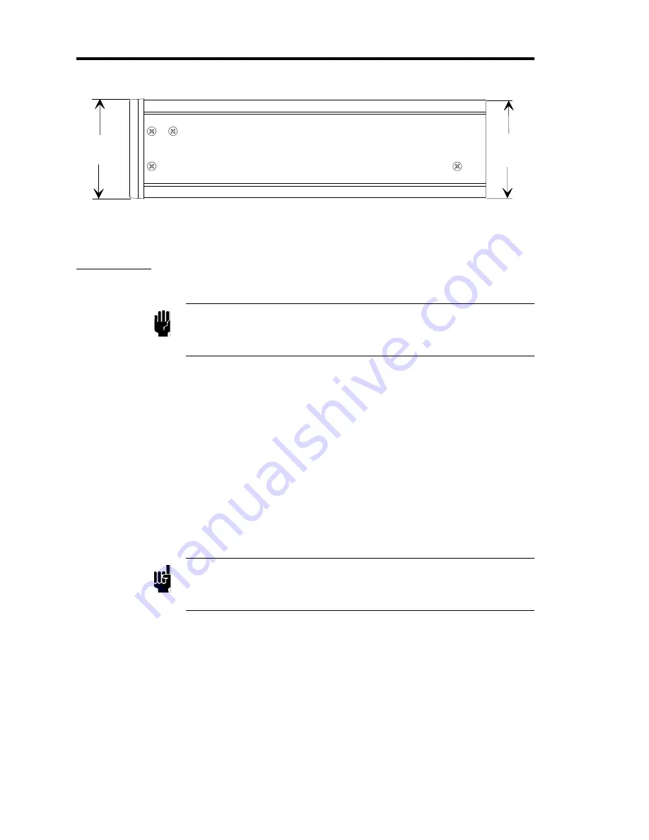
32
3.47
(88.1)
3.38
(85.7)
Figure 8: Side Dimensions
146 Set Up
Caution
Provide proper clearance so that the 146 unit operates within
product environmental specifications (refer to Appendix A: Product
Specifications, page 301).
General
1. Employ proper grounding.
Power, analog and digital commons are all tied together in the 146 power supply. The
transducer signal common and power common are usually tied together internally at the
sensor. Although these commons are connected together internally, it is important that
each ground be used only for its stated purpose to minimize ground noise and ground-
loop errors.
2.
Plug the power cord into a properly grounded electrical outlet to ensure protective
earthing.
Note
If you choose to supply your own power cord you must ensure that it
complies with the applicable national regulatory requirements, such as
UL or CSA.
3. Use a voltmeter to check that the maximum potential difference between the chassis
common and each of the internal grounds is no more than 3.5 Volts.
The chassis common is connected to the 146 internal grounds through several
microfarads of capacitance distributed throughout the unit. It is also clamped with
3.3 Volt, back-to-back, zener diodes shunted by several 0.1 uF capacitors in the power
supply. This arrangement allows some flexibility in configuring an optimum earth-
grounding scheme that is especially important when several transducers are connected to
the 146 unit. The maximum potential difference between these grounds must be limited
to 3.5 Volts to prevent the introduction of noise.
Artisan Technology Group - Quality Instrumentation ... Guaranteed | (888) 88-SOURCE | www.artisantg.com


