
ENGINE MAIN PARTS - INSPECTION AND CORRECTION
2 - 27
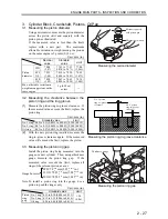
3. Cylinder
Block,
Crankshaft, Pistons, Oil Pan
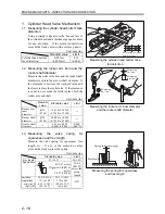
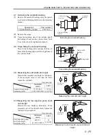
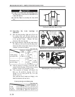
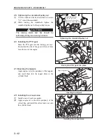
3.1 Measuring the piston diameter
Using a micrometer, measure the piston diameter
across the piston skirt and squarely with the
piston pin, as illustrated.
If the measured value is less than the limit,
replace with a new part. The maximum
allowable variation in weight among the pistons
on the same engine is 5 grams (0.18 oz).
Unit: mm (in.)
Nominal
value
Standard
value
Limit
STD
78.00
(3.07)
77.93 to 77.95
(3.070 to 3.071)
77.80
(3.065)
0.25
OS
78.25
(3.08)
78.18 to 78.20
(3.080 to 3.081)
78.05
(3.075)
Piston
diameter
0.50
OS
78.50
(3.09)
78.43 to 78.45
(3.090 to 3.090)
78.30
(3.085)
Max. allowable variation in
weight among pistons on the
same engine:
5 g (0.18 oz)
or less
―
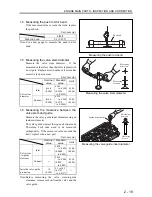
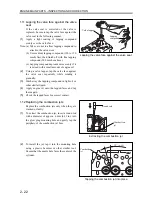
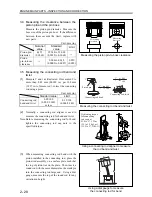
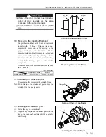
3.2 Measuring the clearance between the
piston ring and the ring groove
(1)
Measure the piston ring-to-groove clearance. If
the measured value exceeds the limit, replace the
piston ring.
Unit: mm (in.)
Standard
value Limit
No. 1 ring 0.09 to 0.11 (0.0035 to 0.0043) 0.300 (0.012)
No. 2 ring 0.07 to 0.11 (0.0028 to 0.0043) 0.200 (0.008)
Oil ring
0.03 to 0.07 (0.0012 to 0.0028) 0.200 (0.008)
(2)
With the new piston ring installed, measure the
ring-to-groove clearance again. If the measured
value still exceeds the limit, replace the piston.
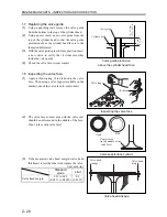
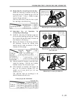
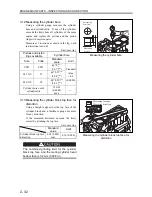
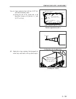
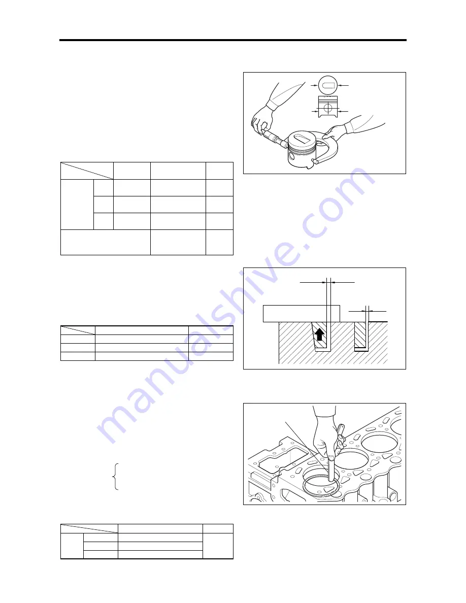
3.3 Measuring the piston ring gap
Install the piston ring being measured into the
gauge or a new cylinder. Then, using a thickness
gauge, measure the piston ring gap. If the
measured value exceeds the limit, replace all
rings of the relevant piston as a set.
STD=78
+0.03
0
mm (3.07
+0.0012
0
in.)
Gauge bore size 25 OS=78.25
+0.03
0
mm (3.08
+0.0012
0
in.)
50 OS=78.50
+0.03
0
mm (3.09
+0.0012
0
in.)
Note: To install a piston ring into the gauge, use a
piston to push the ring evenly.
Unit: mm (in.)
Standard
value
Limit
No. 1 ring 0.15 to 0.30 (0.006 to 0.012)
No. 2 ring 0.15 to 0.35 (0.006 to 0.014)
Piston
ring
gap
Oil ring
0.20 to 0.40 (0.008 to 0.016)
1.50
(0.06)
Measuring the piston diameter
Measuring the piston ring-to-groove clearance
Measuring the piston ring gap
Measuring location
Measure squarely
with piston pin
Thickness gauge
No. 1 piston
ring-to-groove
clearance
No. 2 piston
ring-to-groove
clearance
Содержание diesel engines
Страница 5: ......
Страница 33: ...SERVICE STANDARDS 1 20 ...
Страница 34: ...1 General Tools 1 22 2 Special Tools 1 23 TOOLS LIST ...
Страница 37: ...TOOLS LIST 1 24 ...
Страница 38: ...1 Identifying the Timing for Overhaul 1 26 2 Measuring the Compression Pressure 1 27 OVERHAUL TIMING ...
Страница 41: ...OVERHAUL TIMING 1 28 ...
Страница 46: ......
Страница 47: ......
Страница 61: ...ENGINE MAIN PARTS DISASSEMBLY 2 16 ...
Страница 99: ...FUEL SYSTEM REMOVAL 3 8 ...
Страница 115: ...FUEL SYSTEM DISASSEMBLY INSPECTION AND REASSEMBLY 3 24 ...
Страница 117: ...FUEL SYSTEM INSTALLATION 3 26 1 Fuel Injection Pumps Installing the fuel injection pumps Installation sequence ...
Страница 119: ...FUEL SYSTEM INSTALLATION 3 28 2 Governor Installing the governor Installation sequence ...
Страница 123: ...FUEL SYSTEM INSTALLATION 3 32 ...
Страница 131: ...OIL SYSTEM DISASSEMBLY INSPECTION AND REASSEMBLY 4 8 ...
Страница 143: ...COOLING SYSTEM DISASSEMBLY INSPECTION AND REASSEMBLY 5 8 ...
Страница 150: ......
Страница 151: ......
Страница 153: ...INLET AND EXHAUST SYSTEMS REMOVAL 6 4 ...
Страница 159: ...INLET AND EXHAUST SYSTEMS INSTALLATION 6 10 ...
Страница 160: ...1 Starter 7 2 2 Alternator 7 3 3 Stop Solenoid 7 4 4 Glow Plug 7 5 ELECTRICAL SYSTEM REMOVAL ...
Страница 161: ...ELECTRICAL SYSTEM REMOVAL 7 2 1 Starter Removal of the starter Removal sequence Harness Bolt Starter ...
Страница 164: ...ELECTRICAL SYSTEM REMOVAL 7 5 4 Glow Plug Removal of the glow plug Removal sequence Glow plug Connection plate ...
Страница 165: ...ELECTRICAL SYSTEM REMOVAL 7 6 ...
Страница 184: ...1 Glow Plug 7 26 2 Stop Solenoid 7 27 3 Alternator 7 28 4 Starter 7 29 ELECTRICAL SYSTEM INSTALLATION ...
Страница 189: ...ELECTRICAL SYSTEM INSTALLATION 7 30 ...
Страница 207: ...MISCELLANEOUS 9 4 ...