


OVERHAUL TIMING
1 - 27
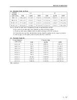
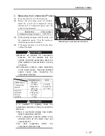
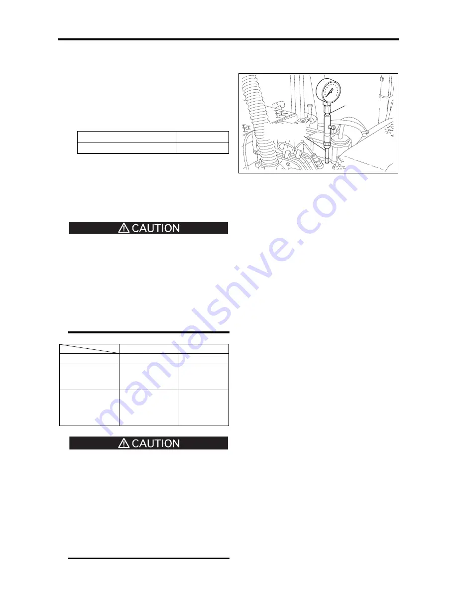
2. Measuring the Compression Pressure
(1)
Move the control lever to STOP position.
(2)
Remove the glow plugs from all cylinders.
Install the special tool Compression Gauge
Adapter and a compression gauge onto the
cylinder being measured.
Special tool
Part number
Compression Gauge Adapter
ST332270
(3)
While cranking the engine with the starter, read
the compression gauge. Note the reading at
which the gauge needle stabilizes.
(4)
If the measured value is at or below the limit,
overhaul the engine.
(a)
Measure all cylinders for compression
pressure. Do not measure only one
cylinder and make assumption about the
other cylinders as this will lead to a wrong
conclusion.
(b)
Compression pressure varies depending
on the engine speed. Keep the specified
engine speed when measuring the
compression pressure.
Standard
value
Limit
Engine speed
290 min
-1
Compression
pressure
2.9 MPa
(30 kgf/cm
2
)
[421 psi]
2.6 MPa
(27 kgf/cm
2
)
[377 psi]
Tolerable
difference
between
cylinders
0.29 MPa
(3.0 kgf/cm
2
)
[42 psi]
or less
It is important to regularly check the
compression pressure so that you can tell the
difference.
・
New or overhauled engines have slightly
higher compression pressure.
・
The compression pressure settles to the
standard value as the piston rings and
valve seats fit in.
・
As wear progresses further, the
compression pressure drops.
Compression
gauge adapter
Compression
gauge
Measuring the compression pressure
Содержание diesel engines
Страница 5: ......
Страница 33: ...SERVICE STANDARDS 1 20 ...
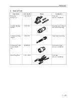
Страница 34: ...1 General Tools 1 22 2 Special Tools 1 23 TOOLS LIST ...
Страница 37: ...TOOLS LIST 1 24 ...
Страница 38: ...1 Identifying the Timing for Overhaul 1 26 2 Measuring the Compression Pressure 1 27 OVERHAUL TIMING ...
Страница 41: ...OVERHAUL TIMING 1 28 ...
Страница 46: ......
Страница 47: ......
Страница 61: ...ENGINE MAIN PARTS DISASSEMBLY 2 16 ...
Страница 99: ...FUEL SYSTEM REMOVAL 3 8 ...
Страница 115: ...FUEL SYSTEM DISASSEMBLY INSPECTION AND REASSEMBLY 3 24 ...
Страница 117: ...FUEL SYSTEM INSTALLATION 3 26 1 Fuel Injection Pumps Installing the fuel injection pumps Installation sequence ...
Страница 119: ...FUEL SYSTEM INSTALLATION 3 28 2 Governor Installing the governor Installation sequence ...
Страница 123: ...FUEL SYSTEM INSTALLATION 3 32 ...
Страница 131: ...OIL SYSTEM DISASSEMBLY INSPECTION AND REASSEMBLY 4 8 ...
Страница 143: ...COOLING SYSTEM DISASSEMBLY INSPECTION AND REASSEMBLY 5 8 ...
Страница 150: ......
Страница 151: ......
Страница 153: ...INLET AND EXHAUST SYSTEMS REMOVAL 6 4 ...
Страница 159: ...INLET AND EXHAUST SYSTEMS INSTALLATION 6 10 ...
Страница 160: ...1 Starter 7 2 2 Alternator 7 3 3 Stop Solenoid 7 4 4 Glow Plug 7 5 ELECTRICAL SYSTEM REMOVAL ...
Страница 161: ...ELECTRICAL SYSTEM REMOVAL 7 2 1 Starter Removal of the starter Removal sequence Harness Bolt Starter ...
Страница 164: ...ELECTRICAL SYSTEM REMOVAL 7 5 4 Glow Plug Removal of the glow plug Removal sequence Glow plug Connection plate ...
Страница 165: ...ELECTRICAL SYSTEM REMOVAL 7 6 ...
Страница 184: ...1 Glow Plug 7 26 2 Stop Solenoid 7 27 3 Alternator 7 28 4 Starter 7 29 ELECTRICAL SYSTEM INSTALLATION ...
Страница 189: ...ELECTRICAL SYSTEM INSTALLATION 7 30 ...
Страница 207: ...MISCELLANEOUS 9 4 ...