ENGINE MAIN PARTS - INSPECTION AND CORRECTION
2 - 21
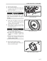
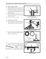
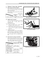
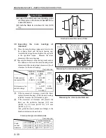
(4)
If the measured valve head sinkage exceeds the
limit, correct the valve seat or replace the
cylinder head assembly.
Unit: mm (in.)
Standard
value
Limit
Valve head sinkage
0.25 to 0.75
(0.0098
±
0.0295)
1.5
(0.0600)
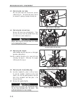
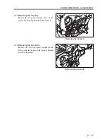
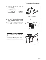
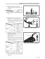
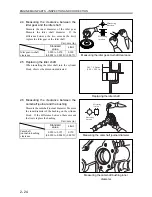
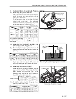
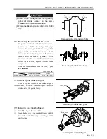
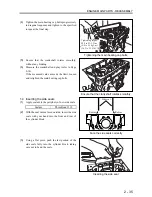
1.9 Correcting the valve face
If the valve face is excessively worn, correct with
a valve refacer.
Note: (a) When grinding, set the refacer at 45º relative
to the valve face.
(b) The valve head margin should be maintained
above the limit. If it appears that the
minimum margin cannot be maintained after
refacing, replace the valve.
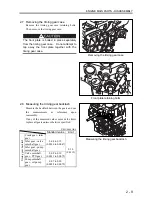
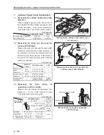
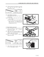
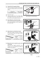
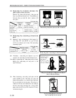
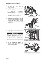
1.10 Correcting the valve seat
(1)
Before correcting the valve seat, check the valve
stem-to-guide clearance and, if necessary,
replace the valve guide.
(2)
Grind with a valve seat cutter (available on the
market) or a valve seat grinder until the valve seat
width and angle meet specification.
Note:
Valve seat correction should be limited as
minimum as possible.
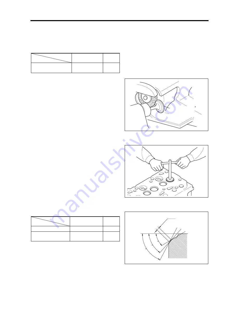
Unit: mm (in.)
Standard
value
Limit
Valve seat angle
45°
―
Valve seat width
1.30 to 1.80
(0.0512 to 0.0709)
2.5
(0.0985)
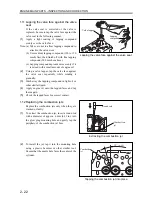
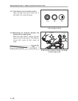
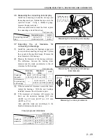
(3) After correction, lap the valve face against the
valve seat using lapping compound.
Correcting the valve face
Correcting the valve seat
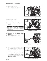
Valve seat angle and width
Refacer set at 45
relative to the
valve face
Valve contact width
1.3 to 1.8 mm
(0.05 to 0.07 in.)
60
45
30
Содержание diesel engines
Страница 5: ......
Страница 33: ...SERVICE STANDARDS 1 20 ...
Страница 34: ...1 General Tools 1 22 2 Special Tools 1 23 TOOLS LIST ...
Страница 37: ...TOOLS LIST 1 24 ...
Страница 38: ...1 Identifying the Timing for Overhaul 1 26 2 Measuring the Compression Pressure 1 27 OVERHAUL TIMING ...
Страница 41: ...OVERHAUL TIMING 1 28 ...
Страница 46: ......
Страница 47: ......
Страница 61: ...ENGINE MAIN PARTS DISASSEMBLY 2 16 ...
Страница 99: ...FUEL SYSTEM REMOVAL 3 8 ...
Страница 115: ...FUEL SYSTEM DISASSEMBLY INSPECTION AND REASSEMBLY 3 24 ...
Страница 117: ...FUEL SYSTEM INSTALLATION 3 26 1 Fuel Injection Pumps Installing the fuel injection pumps Installation sequence ...
Страница 119: ...FUEL SYSTEM INSTALLATION 3 28 2 Governor Installing the governor Installation sequence ...
Страница 123: ...FUEL SYSTEM INSTALLATION 3 32 ...
Страница 131: ...OIL SYSTEM DISASSEMBLY INSPECTION AND REASSEMBLY 4 8 ...
Страница 143: ...COOLING SYSTEM DISASSEMBLY INSPECTION AND REASSEMBLY 5 8 ...
Страница 150: ......
Страница 151: ......
Страница 153: ...INLET AND EXHAUST SYSTEMS REMOVAL 6 4 ...
Страница 159: ...INLET AND EXHAUST SYSTEMS INSTALLATION 6 10 ...
Страница 160: ...1 Starter 7 2 2 Alternator 7 3 3 Stop Solenoid 7 4 4 Glow Plug 7 5 ELECTRICAL SYSTEM REMOVAL ...
Страница 161: ...ELECTRICAL SYSTEM REMOVAL 7 2 1 Starter Removal of the starter Removal sequence Harness Bolt Starter ...
Страница 164: ...ELECTRICAL SYSTEM REMOVAL 7 5 4 Glow Plug Removal of the glow plug Removal sequence Glow plug Connection plate ...
Страница 165: ...ELECTRICAL SYSTEM REMOVAL 7 6 ...
Страница 184: ...1 Glow Plug 7 26 2 Stop Solenoid 7 27 3 Alternator 7 28 4 Starter 7 29 ELECTRICAL SYSTEM INSTALLATION ...
Страница 189: ...ELECTRICAL SYSTEM INSTALLATION 7 30 ...
Страница 207: ...MISCELLANEOUS 9 4 ...