FUEL SYSTEM - DISASSEMBLY, INSPECTION AND REASSEMBLY
3 - 21
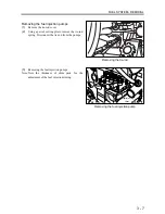
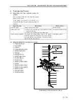
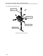
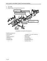
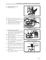
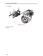
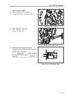
3.2 Reassembling the governor
(1)
Install the levers first.
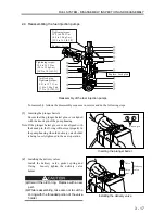
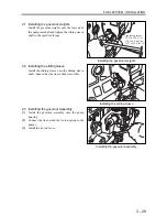
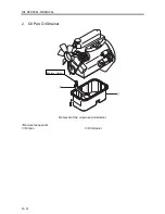
(2)
Install the O-ring onto the governor shaft.
(3)
Insert the governor shaft into the governor case,
and combine it with the levers.
(4)
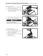
Hold the grooved pin and the spring pin in place,
and knock them in with a soft hammer.
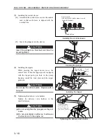
(5)
Install the tie-rod and the tie-rod spring.
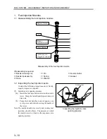
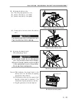
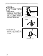
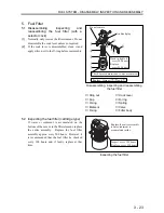
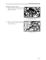
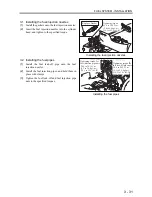
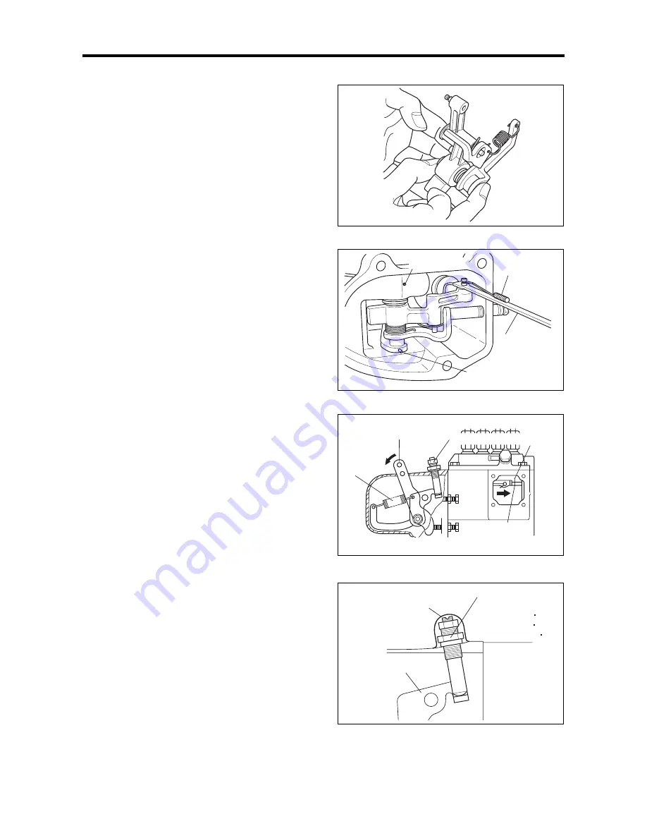
3.3 Installing the torque spring set
Prior to installation, adjust the low and high idle
speeds of engine. Stop the engine for installation
and adjustment of the torque spring set.
(1)
Remove the tie-rod cover.
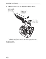
(2)
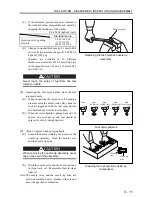
Pull the speed control lever to the high idle speed
position and hold it there.
(3)
Pull the tie-rod in the direction of the arrow until
a slight resistance is felt.
Note: This is the initial resistance by the governor
spring. Do not pull the tie-rod further to try to
overcome the resistance.
(4)
While holding the tie-rod in this position, screw
in the torque spring set until the notched line on
the control rack is aligned with that on the pump
body.
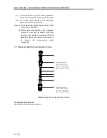
(5)
With both notched lines aligned, lock the torque
spring set by tightening the special nut to the
specified torque.
(6)
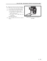
Place the torque set sealing cap over the torque
spring set, and stake it in place.
Installing the levers
Assembling the governor
Installing the torque spring set
Grooved pin
Tie-rod spring
Tie-rod
Spring pin
Speed
control
lever
Governor
spring
Torque
spring
set
Notched line on
control rack
Notched line on pump body
Adjusting and sealing the torque spring set
Sealing cap
Special nut
Governor lever
Tightening torque:
14.7 to 24.5 N m
(1.5 to 2.5 kgf m)
[10.8 to 18.1 lbf ft]
Содержание diesel engines
Страница 5: ......
Страница 33: ...SERVICE STANDARDS 1 20 ...
Страница 34: ...1 General Tools 1 22 2 Special Tools 1 23 TOOLS LIST ...
Страница 37: ...TOOLS LIST 1 24 ...
Страница 38: ...1 Identifying the Timing for Overhaul 1 26 2 Measuring the Compression Pressure 1 27 OVERHAUL TIMING ...
Страница 41: ...OVERHAUL TIMING 1 28 ...
Страница 46: ......
Страница 47: ......
Страница 61: ...ENGINE MAIN PARTS DISASSEMBLY 2 16 ...
Страница 99: ...FUEL SYSTEM REMOVAL 3 8 ...
Страница 115: ...FUEL SYSTEM DISASSEMBLY INSPECTION AND REASSEMBLY 3 24 ...
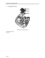
Страница 117: ...FUEL SYSTEM INSTALLATION 3 26 1 Fuel Injection Pumps Installing the fuel injection pumps Installation sequence ...
Страница 119: ...FUEL SYSTEM INSTALLATION 3 28 2 Governor Installing the governor Installation sequence ...
Страница 123: ...FUEL SYSTEM INSTALLATION 3 32 ...
Страница 131: ...OIL SYSTEM DISASSEMBLY INSPECTION AND REASSEMBLY 4 8 ...
Страница 143: ...COOLING SYSTEM DISASSEMBLY INSPECTION AND REASSEMBLY 5 8 ...
Страница 150: ......
Страница 151: ......
Страница 153: ...INLET AND EXHAUST SYSTEMS REMOVAL 6 4 ...
Страница 159: ...INLET AND EXHAUST SYSTEMS INSTALLATION 6 10 ...
Страница 160: ...1 Starter 7 2 2 Alternator 7 3 3 Stop Solenoid 7 4 4 Glow Plug 7 5 ELECTRICAL SYSTEM REMOVAL ...
Страница 161: ...ELECTRICAL SYSTEM REMOVAL 7 2 1 Starter Removal of the starter Removal sequence Harness Bolt Starter ...
Страница 164: ...ELECTRICAL SYSTEM REMOVAL 7 5 4 Glow Plug Removal of the glow plug Removal sequence Glow plug Connection plate ...
Страница 165: ...ELECTRICAL SYSTEM REMOVAL 7 6 ...
Страница 184: ...1 Glow Plug 7 26 2 Stop Solenoid 7 27 3 Alternator 7 28 4 Starter 7 29 ELECTRICAL SYSTEM INSTALLATION ...
Страница 189: ...ELECTRICAL SYSTEM INSTALLATION 7 30 ...
Страница 207: ...MISCELLANEOUS 9 4 ...