background image

Graphic Operation Terminal GOT-F900

HPP Mode 10

10-8

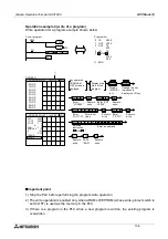
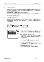
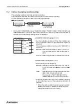
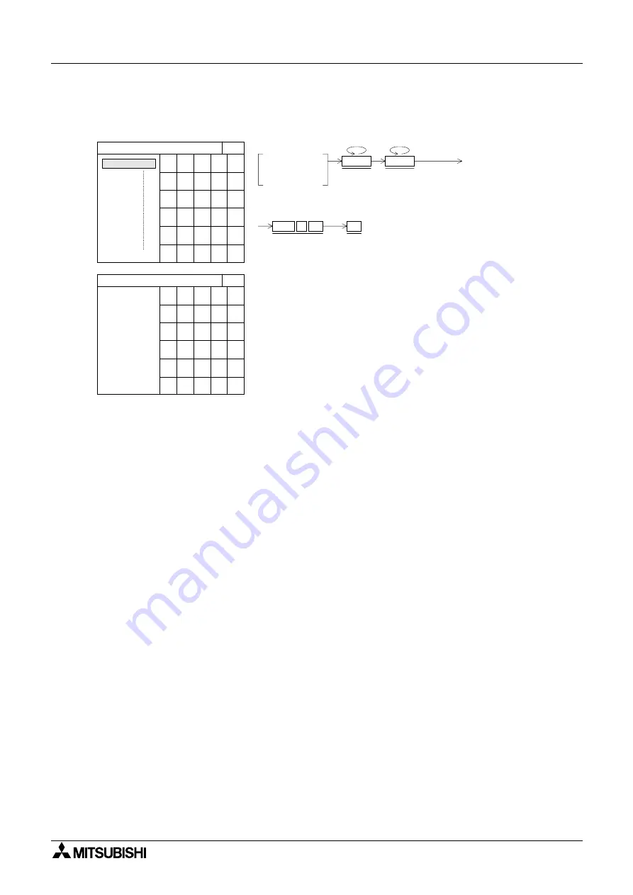
Operation example 3 (program all clear)
Program all clear operation

n

n

n

n

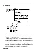
Important point

1) Stop the PLC before performing the program all clear operation.

2) The all clear operation is enabled only when a RAM or EEPROM (whose write-protect

switch is set to OFF) is used as the memory in the PLC.

MODE

Display
<READ>
in 1).

MORE

Key operation

Change the key
indication to display
the NOP key.

PROGRAM LIST
screen is
displayed.

GO

Execute
program
all clear.

  0 LD   X000

[ PROGRAM LIST ]

END

  1

<WRITE>

[ PROGRAM LIST ]

END

<WRITE>

SCREEN

  2
  3
  4
  5
  6
  7
  8
  9

0 NOP
1 NOP
2 NOP
3 NOP
4 NOP
5 NOP
6 NOP
7 NOP
8 NOP
9 NOP

A

Designate the
program all
clear operation.

NOP

GO

Содержание F930GOT-BWD

Страница 1: ...OPERATION MANUAL GOT F900 ...

Страница 2: ...and understood If in doubt at any stage of the installation of GOT F900 always consult a professional electrical engineer who is qualified and trained to the local and national standards which apply to the installation site If in doubt about the operation or use of GOT F900 please consult the nearest Mitsubisi Electric distributor This manual is subject to change without notice Graphic Operation T...

Страница 3: ...i GRAPHIC OPERATION TERMINAL GOT F900 OPERATION MANUAL Manual number JY992D94701 Manual revision A Date April 2001 Graphic Operation Terminal GOT F900 ...

Страница 4: ...Graphic Operation Terminal GOT F900 ii ...

Страница 5: ...07 278 695 Please tick the box of your choice What condition did the manual arrive in Good Minor damage Unusable Will you be using a folder to store the manual Yes No What do you think to the manual presentation Tidy Unfriendly Are the explanations understandable Yes Not too bad Unusable Which explanation was most difficult to understand Are there any diagrams which are not clear Yes No If so whic...

Страница 6: ...Graphic Operation Terminal GOT F900 iv ...

Страница 7: ...ll operators of the completed equipment should be trained to use that product in a safe and coordinated manner in compliance to established safety practices The operators should also be familiar with documentation which is connected with the actual operation of the completed equipment Note Note the term completed equipment refers to a third party constructed device which contains or uses the produ...

Страница 8: ...quipment All examples and diagrams shown in this manual are intended only as an aid to understanding the text not to guarantee operation Mitsubishi Electric will accept no responsibility for actual use of the product based on these illustrative examples Owing to the very great variety in possible application of this equipment you must satisfy yourself as to its suitability for your specific applic...

Страница 9: ...ion 5 1 5 2 Installation 5 2 6 Function 6 1 6 1 Function list 6 1 7 Start up 7 1 7 1 Start up procedure 7 1 7 2 Operation environment setting 7 3 7 3 Each mode selection procedure 7 9 7 4 Security function screen protection function 7 11 7 4 1 Upgrading of security function 7 13 8 Creation of Display Screens 8 1 8 1 Outline of compatibility of screen data 8 2 8 1 1 Functions dedicated to screen cr...

Страница 10: ...ment monitor 10 12 10 4 2 Changing set values and current values of T C and D 10 14 10 4 3 Forced ON OFF 10 16 10 5 LIST MONITOR 10 17 10 6 ACTIVE STATE MONITOR 10 18 10 7 BFM MONITOR 10 19 10 8 PC DIAGNOSIS 10 20 11 Sampling Mode 11 1 11 1 Outline of sampling mode 11 1 11 2 Outline of sampling condition setting 11 3 11 2 1 SAMPLE COND 11 5 11 2 2 START COND 11 6 11 2 3 END COND 11 7 11 2 4 SAMPLI...

Страница 11: ...rt and abortion by touch switches 16 2 16 3 3 Hard copy output signal GT Designer 16 3 16 3 4 Printing image 16 5 17 Observe status function 17 1 17 1 Outline of observe status function 17 1 17 2 Applicable version 17 2 17 3 Observe status cycle 17 2 17 4 Setting the triggers 17 2 17 4 1 Setting the operation 17 3 17 5 Trigger and number of devices 17 6 17 6 Cautions 17 7 17 7 Use example utilizat...

Страница 12: ...of Display Screen FX PCS DU WIN E 19 1 19 1 Outline of changeover of display screen 19 1 19 2 Change Screen object 19 2 19 2 1 Contents of setting 19 2 19 2 2 Operation of screen changeover 19 4 19 2 3 Timing of screen changeover 19 5 19 3 Screen changeover by touch key 19 6 19 4 Screen changeover from PLC 19 9 19 4 1 Screen changeover using bit devices 19 9 19 4 2 Screen changeover by data 19 11 ...

Страница 13: ...isplay screen 21 1 21 2 Changeover of display screen 21 2 21 2 1 Contents of setting 21 2 21 2 2 Contents of screen changeover operation 21 2 21 3 Changeover of base screen changeover from PLC 21 3 21 3 1 Outline of changeover of base screen 21 3 21 3 2 Example of basescreen changeover 21 4 21 4 Screen changeover by touch key 21 5 21 4 1 Changeover using a fixed value 21 5 21 4 2 Changeover to upp...

Страница 14: ...Graphic Operation Terminal GOT F900 Contents xii ...

Страница 15: ...ations for the specifications installation and maintenance etc of F940WGOT Series graphic operation terminals SW D5C GOTR PACKE OPERATING MANUAL supplied with screen creation software This manual contains explanations for the operation of GT Designer SW D5C GOTR PACKE screen design software FX PCS DU WIN E SOFTWARE MANUAL supplied with screen creation software JY992D68301 This manual contains expl...

Страница 16: ...Graphic Operation Terminal GOT F900 Manual configuration and various data 2 MEMO ...

Страница 17: ...nd SWoD5C GOTRE PACK o indicates a numeric not less than 1 can be used to create user screens Display function Up to 500 user defined screens can be displayed In screen creation two or more screens can be overlaid or changed over arbitrarily Simple graphics such as straight lines circles and rectangles can be displayed along with numerics and English Japanese Chinese and Korean text Also bitmaps c...

Страница 18: ...Sampling data can be output to a printer in the form of list Alarm function Alarm messages can be assigned to up to 256 consecutive bit devices in the PLC When a bit device becomes ON the assigned message is displayed overlapped on the user screen In addition a specified user screen can be displayed by setting a corresponding bit device to ON When a bit device becomes ON a corresponding message is...

Страница 19: ...rammable controllers of other companies may be abbreviated as programmable controller or PLC 2 The software kit to create display screens FX PCS DU WIN E or GT Designer may be abbreviated as screen creation software 3 A general purpose computer may be abbreviated as PC 4 A floppy disk may be abbreviated as FD A floppy disk drive may be abbreviated as FDD 5 The graphic operation terminal GOT F900 S...

Страница 20: ...hen an arbitrary numeric within the range of 0 to 9 is to be entered the following expression may be used 1 3 2 Basic operations The common operations in the GOT are shown below a Function display The selected mode or function is displayed here b END key This key terminates the displayed function and returns to the previous screen c CLR clear key This key cancels the input of characters and numeri...

Страница 21: ...oards manufactured by other companies When connected to a PLC or microcomputer board manufactured by other companies the 2 port interface function of the GOT cannot be used F930GOT F940GOT F943GOT and F940WGOT graphic operation terminals Data transfer cable FX 232CAB 1 3 m when the RS 232C port in the PC is 9 pin type Data transfer cable FX 232CAB 2 3m when the RS 232C port in the PC is half pitch...

Страница 22: ...red by Mitsubishi Erectric When a communication unit is used settings for direct connection to CPU should be made F930GOT V2 00 or later should be used F940GOT and F943GOT V3 00 or later should be used When a version is former than V3 00 and computer link connection is made only setting for computer link for A Series is available F940WGOT any version may be used MELSEC Q Series manufactured by Mit...

Страница 23: ...ould be used F940WGOT any version may be used SLC500 Series manufactured by Allen Bradley Co Inc F930GOT V2 00 or later should be used F940GOT and F943GOT V5 00 or later should be used F940WGOT any version may be used MicroLogix 1000 1200 1500 Series manufactured by Allen Bradley Co Inc F930GOT V4 00 or later should be used F940GOT and F943GOT V5 00 or later should be used F940WGOT any version may...

Страница 24: ...1 8 In the case of F943GOT connection to a PLC is limited to RS 232C communication The types connectable through RS 422 communication shown in the table above are not applicable For the method of wiring to a PLC refer to GOT F900 SERIES HARDWARE MANUAL ...

Страница 25: ...kawa Electric Corp V4 00 Addition of function connecting to MicroLogix 1000 1200 1500 Series manufactured by Allen Bradley Co Inc Addition of function connecting to CS1 Series CS1G H CPU V1 manufactured by Omron Corp Connection condition Link connection Addition of function entering numeric values including decimal points Addition of security function screen protection V4 20 Addition of function c...

Страница 26: ...radley Co Inc Addition of function connecting to CS1 Series CS1G H CPU V1 manufactured by Omron Corp Connection condition Link connection Addition of function entering numeric values including decimal points Addition of security function screen protection V6 20 Addition of function connecting to MELSEC positioning units FX 10 20GM FX2N 10 20GM E 20GM Addition of function connecting to inverter FRE...

Страница 27: ...ing to SLC500 Series manufactured by Allen Bradley Co Inc Addition of function hard copy setting on F940GOT display screen Addition of graphic type to touch key and lamp label object V2 41 Addition of hatching pattern of rectangle and circle object Addition of line type straight line and rectangle object Compatible with European font display Addition of function connecting to Q Series PLC Addition...

Страница 28: ...o C Series manufactured by Omron Corp Addition of function connecting to microcomputer SW1D5C H Usable for F930GOT Addition of function connecting to bar code reader Addition of function connecting to SLC500 Series manufactured by Allen Bradley Co Inc SW2D5C A Addition of hard copy function SW5D5C F V5 05F Compatible with connecting to MicroLogix 1000 1200 1500 Series manufactured by Allen Bradley...

Страница 29: ...g element settings Transfer between the screen creation software and GOT is done between RAM area and the flash memory Neither RAM area nor Time now is read to the personal computer The systems requirements can be set with the GOT main unit a default content is stored in RAM or the screen creation software a set content is preserved in flash memory The content set later is given priority User set ...

Страница 30: ...Graphic Operation Terminal GOT F900 Introduction 1 1 14 MEMO ...

Страница 31: ...orms to IEC 1131 2 Frequency Acceleration Amplitude 10 times in each of X Y and Z directions for 80 minutes With intermittent vibration 10 to 57Hz 0 075mm 57 to 150Hz 9 8m s2 With continuous vibration 10 to 57Hz 0 035mm 57 to 150Hz 4 9m s2 Shock resistance Conforms to IEC 1131 2 147m s2 3 times in each direction X Y and Z Noise resistance 1 000Vp p 1µs 30 to 100Hz tested by noise simulator Withsta...

Страница 32: ...ed term is 1 year Back light Cold cathode life of 50 000 hours or more at 25 C 77 F Cold cathode life of 40 000 hours or more at 25 C 77 F Cold cathode life of 40 000 hours or more at 25 C 77 F Guaranteed term is 1 year Key Number of keys used Touch key Max 50 keys 1 screen Configuration Horizontal Vertical 15 4 matrix configuration 20 12 matrix configuration 30 12 matrix configuration last column...

Страница 33: ...1 3 3 5 2 4 P O W E R G R I P S W 1 5 6 6 1 4 1 7 2 6 7 1 1 9 1 7 4 5 5 0 5 1 9 9 1 3 0 5 1 F940GOT F943GOT F930GOT F940WGOT Dimensions mm inches MASS F930GOT 0 3kg 0 66lbs F940GOT F943GOT 1kg 2 2lbs F940WGOT 1kg 2 2lbs Handy GOT 0 79kg 1 74lbs Accessory F930GOT F940GOT F943GOT F940WGOT Mouting brackets Tightning bolt M3 0 12 4bolts packing seal for dust and water resistance Handy GOT Sheets to ch...

Страница 34: ...Graphic Operation Terminal GOT F900 Outside dimensions 3 3 2 MEMO ...

Страница 35: ...ly and by 1 to 4 times horizontally 4 2 Rear panel 1 Power terminal Used to supply power to the GOT and for grounding 2 Battery Used to store sampling data alarm history and current time Screen data is stored in the built in flash memory for which no battery power is needed 3 Extension interface Used to connect optional extension devices A F9GT 40UMB type data transfer adapter is connected to tran...

Страница 36: ...on which the ladder support software has been started can be connected 3 Port for PLC RS 232C connector D sub 9 pin male Used for RS 232C connection to a PLC or microcomputer board Also used to connect two or more GOT units RS 232C connection or for communication with a bar code reader or printer 4 Port for PC F940WGOT RS 232C connector D sub 9 pin male For connection to PC when transferring scree...

Страница 37: ...ting to a PLC through a computer link unit the connector 1 2 or 3 should be used When two or more GOT units are connected 2 system connection cannot be made It is not possible to connect two or more PLCs to one GOT PLC GOT GOT GOT GOT PLC GOT GOT GOT GOT PLC GOT PLC ...

Страница 38: ...Graphic Operation Terminal GOT F900 Part names 4 4 4 MEMO ...

Страница 39: ...low Unit mm inches Make sure that the processing accuracy is 0 to 1 mm 0 to 0 04 Make sure that the thickness of the installation panel is 5 mm or less F930GOT F940GOT F943GOT F940WGOT W 137 5 39 153 6 02 206 8 11 H 66 2 60 121 4 76 124 4 88 W H H 2 W 2 S p a c e f o r m e t a l f i x t u r e Graphic Operation Terminal GOT F900 ...

Страница 40: ...e front of the panel face a GOT b Packing seal c Installation hole 2 Fixing the GOT Hang the hook of the metal fixture offered as accessory to installation hook holes in the GOT Tighten the bolt offered as accessory securely in each position The GOT can be fixed in just four positions at each corner However to prevent dusts and water fix the GOT in all six posi tions excluding the F930GOT a Metal ...

Страница 41: ... 4 V D C 9 0 3 5 2 3 0 9 1 2 3 0 9 1 1 3 6 5 3 5 8 5 3 3 5 7 5 2 9 5 5 0 2 0 o r l e s s 9 0 3 5 4 8 5 1 9 0 2 3 0 9 1 2 4 V D C 1 4 0 5 5 1 1 3 0 5 1 2 6 5 0 2 5 1 0 0 3 9 1 0 0 3 9 6 5 0 2 5 5 0 2 0 2 3 0 9 1 2 3 0 9 1 1 5 2 5 9 8 2 4 V D C 2 3 0 9 1 1 0 0 3 9 1 0 0 3 9 7 0 6 2 7 8 3 4 5 1 3 5 3 4 5 1 3 5 5 0 2 0 o r l e s s 2 0 5 8 0 7 2 3 0 9 1 2 3 0 9 1 5 0 1 9 6 1 4 3 5 6 3 1 3 3 5 2 4 F930G...

Страница 42: ...Graphic Operation Terminal GOT F900 Installation 5 5 4 MEMO ...

Страница 43: ...t devices in the PLC are controlled Controll can be in the format of momentary alternate or set reset Screen changeover The display screen can be changed over The PLC or touch key can be used to change over the display screen Data batch transfer Data saved in the GOT can be transferred to the PLC Security function Screens are displayed only when the proper password is entered This function is avai...

Страница 44: ...history is deleted Test mode Screen list User screens are displayed in order of screen No 13 Data file The data used in the recipe function data file transfer function is changed Debug operation The operations are checked to know whether key operations screen changeover etc have been correctly performed on the displayed user screen Communication monitor The status of communication with the connect...

Страница 45: ...ey Turn on the power while pressing the touch key The OPENING SCREEN is displayed The SET UP MODE screen is displayed A user screen is displayed When there is no screen data Perform wiring of the power supply unit of the GOT Connect the GOT and the PLC with an optional connection cable Turn on the power of the GOT If the SET UP screen is required When turning on the power press and hold the top le...

Страница 46: ...s displayed The SELECT MODE screen is displayed Each menu item on the screen functions as a touch key When a desired one is pressed the corresponding mode is selected This SELECT MODE screen can be called also by pressing a corner of the screen set in MAIN MENU CALL KEY on the SET UP MODE screen The selected mode screen is displayed If the menu call key is not set in MAIN MENU CALL KEY on the SET ...

Страница 47: ...LC type c SERIAL PORT To be selected when a printer is connected to the GOT or when communication is performed between the GOT and a micro computer board d OPENING SCREEN Allows setting of the duration in which the OPENING SCREEN is displayed immediately after the power is turned ON e MAIN MENU CALL KEY Allows setting of the position of the touch key which calls the SELECT MODE screen from the scr...

Страница 48: ...nt point When the items a to e g and h above are set in the GOT and screen data is transferred from the screen creation software the operation environment setting selected in the screen creation software becomes valid In such a case set the operation environment in the GOT again or align from the beginning the setting of the items a to e g and h above with that in the screen creation software An e...

Страница 49: ...U PORT The GOT is connected directly to the program port in the PLC RS 422 or RS 232C The FX Series the A Series a motion controller and the N Series are available LINK PORT RS422 The GOT performs communication in accordance with the RS 422 via a link unit The A Series the C Series and the N Series are available LINK PORT RS232C The GOT performs communication in accordance with the RS 232C via a l...

Страница 50: ... the power is turned on Initial 4sec When the touch key DISPLAY TIME is pressed the time can be set using the ten key pad displayed at the bottom of the screen Enter the desired display time using the ten key pad displayed at the bottom of the screen then press the ENT key to register the input time If DISPLAY TIME is set to 0 the screen mode is selected immediately after the power is turned on an...

Страница 51: ...t tom of the screen Enter the desired date or time and press the ENT key to register it Set the time at which the display backlight turns off When a touch key is not pressed or the user screen is not changed over within the specified OFF time the backlight is turns off Initial 10 min When OFF TIME is pressed the OFF time can be set within the range of 0 to 99 minutes using the ten key pad displaye...

Страница 52: ... pressed the LCD becomes brighter Initial The middle The screen data stored in the GOT can be cleared When YES is selected the message NOW CLEARING USER DATA is displayed and key is accepted When the message DISPLAY SCREEN IS NOT AVAILABLE is displayed the data is cleared completely After that the screen mode is automatically selected BUZZER END BUZZER BUZZER OFF BUZZER ON LCD CONTRAST END LCD CON...

Страница 53: ...ODE screen shown on the left is displayed The outline of each mode and the selection procedure are described below USER SCREEN MODE Refer to Sections 9 A user screen is displayed Characters such as standard text numerics Katakana and Kanji and simple graphic can be displayed HPP MODE Refer to Section 10 List programs can be read written monitored and bit devices and word devices in the PLC can be ...

Страница 54: ...WITCH DATA TRANSFER TEST MODE OTHER MODE TEST MODE Refer to Section 13 The contents of the user screens can be confirmed In addition data files can be edited and debugging can be performed OTHER MODE Refer to Section 14 Setting of the time switch printer output entr y code operation procedure etc can be performed ...

Страница 55: ...lent to or lower than the entered code 2 Input of entry code To enter code the entry code input screen should be displayed To display the entry code input screen a touch key should be provided on the screen To set this touch key enter FF68 to the key code When the touch key is pressed the entry code input screen is displayed When a screen whose entry code level is higher is tried to be displayed a...

Страница 56: ...is case Screen 1 is displayed when the power is turned on Level 0 When an entry code 222 is entered Screens 1 to 3 can be displayed and manipulated When an entry code 444 is entered while Screens 1 to 3 are displayed Screens 1 to 5 can be displayed and manipulated When the entry code is reset while Screens 1 to 5 are displayed Screen 1 is displayed initial status In the use example shown above the...

Страница 57: ...signer SW5D5C GOTR PACK 1 The following window can be displayed by using Common Password Entry code input and contents of error message Product model name Version F930GOT V4 00 F940 F943GOT V6 00 F940WGOT V1 00 Software name Applicable version GT Designer SW1D5C GOTR PACK V5 05F FX PCS DU WIN E V2 00 Error message Password is incorrect When the entered entry code is incorrect Enter the correct ent...

Страница 58: ... level of the system screens No 1000 to 1030 was fixed at 15 Now it is possible to set the security level of the system screens by make setting as shown below Setting for GT Designer SW5D5C GOTR PACK 1 The window shown below can be displayed by using Common Auxiliary setting Screen 2 When Use sequrity level of utility screen at the bottom of the window is checked it becomes possible to set the Uti...

Страница 59: ... Windows95 Windows98 Windows NT R 4 0 F940GOT F943GOT SW1D5C GOTR PACKE E or later F930GOT SW1D5C GOTR PACKE H or later F940WGOT To be released 2Q2001 a Data can be read from and written to the GOT using FX PCS DU WIN E b Data can be read from and written to the GOT using GT Designer This section describes the compatibility of data when these screen creation software are used For the operating pro...

Страница 60: ...nctions of the GOT supported only by FX PCS DU WIN E These functions cannot be read or written using GT Designer Common functions Refer to Paragraph 8 1 2 Functions supported by both FX PCS DU WIN E and GT Designer However some function names are different and some functions are restricted in each software Functions dedicated to GT Designer Refer to Paragraph 8 1 3 Functions supported only by GT D...

Страница 61: ...s of 16 16 bits created by the user can be used Data change The ten key keypad can be displayed by pressing a touch key Lamp screen When a bit device in the PLC becomes ON a specified screen is over laid on the current screen 2 Device comment This device monitor function in HPP mode is used to display comments instead of devices 3 Creation of display screen for F940WGOT Note When the functions 1 t...

Страница 62: ...tting is permitted Ascii Display ßWhen setting is forbidden Ascii Ascii Input ßWhen setting is permitted Comment In case of word deviceà Library Text In case of bit deviceà Text Indicator Part Display In case of word deviceà Library Image In case of bit deviceà Image Indicator Lamp Label Indicator Panelmeter Shape displayed on screen is different Panel Meter Circle Graph Clock Date Time Trend Samp...

Страница 63: ... bit momentary Names are different Switch momentary bit ALT Switch alternate bit SET Switch set bit RST Switch reset Base changeover ßBit condition etc cannot be converted Change Screen Word operation Indirect Fixed value Names are different Increment Indirect Fixed value Decrement Fixed value Write Constant Name in GT Designer Difference in set item attribute Name in FX PCS DU WIN E Parts Only bi...

Страница 64: ...rmed only while the gain and offset are specified that is while the arithmetic operation formula is fixed Display trigger Only Always is available as the display trigger except in line graphs the display trigger is used to specify the sampling cycle Range specification The color and the blink attribute cannot be changed over by a value of a word device Only the range in the normal status can be sp...

Страница 65: ...bar graphs and meters Paint Paints fills a specified area which may be a polygon In the F900GOT boxes and circles can be filled Data List Displays the data list in the form of a table Level Displays the level within a specified image range In the F900GOT the level can be expressed in the form of bar graph box Part Movement Moves displayed parts on a specified trace 2 Printer output Report Outputs ...

Страница 66: ...raph 8 1 1 a FX PCS DU WIN E No problems are expected in both read and write b GT Designer If the GOT has dedicated functions such functions are not read Setting of display screen changeover Refer to Paragraph 8 1 2 a FX PCS DU WIN E Names and contents of the functions are automatically converted into those used in the software b GT Designer Names and contents of the functions are automatically co...

Страница 67: ...n the common setting screen in FX PCS DU WIN E are treated as screen No 501 in GT Designer However screen No 501 is treated as a user screen so the contents of screen No 501 are not shared by all screens in the same way as FX PCS DU WIN E The screen overlay function overlap window 1 or 2 or the screen call function should be used so that the contents of screen No 501 are shared by all screens Back...

Страница 68: ... the alarm notification method selected in the head alarm device in the 50DU is adopted for every alarm 2 Display of user screens a Image Library Image and Image Indicator When a black and white image is selected to be used with the functions above it can be displayed in colors other than black and white in the 50DU by specifying the colors In the F940GOT the same operation can be performed using ...

Страница 69: ...s wide by 20 dots high F940WGOT 30 12 matrix configuration 16 dots wide by 20 dots high last column composed of 14 dots 8 5 2 Number of display screens and screen Nos Up to 500 screens can be displayed A screen No is assigned to each display screen When FX PCS DU WIN E is used Nos 0 to 499 When GT Designer is used Nos 1 to 500 Alt though the first screen No is different it is automatically convert...

Страница 70: ...r size 1 character 16 8 dots V H In the case of the following versions or later high definition fonts 4 or more and small character fonts 6 8 dots can be displayed For further details refer to the next page Corresponding version GOT Screen creation software Product model name Version F930GOT V4 10 F940 F943GOT V6 10 F940WGOT V1 10 Software GT Designer SW5D5C GOTR PACK V5 05F FX PCS DU WIN E V2 50 ...

Страница 71: ...t 6 8 dots font 6 8 dots font display is available only when the following objects and sizes are selected and setting for 6 8 dots font is made using the screen creation software Applicable condition Applicable object Comment display Lamp display Date Time display Alarm list display Alarm history display ASCII display ASCII input Numeric value display Numeric input Touch switch 6 8 dots font can n...

Страница 72: ...d GT Designer colors can be specified according to the display unit F930GOT 2 colors black and white F940GOT F943GOT 8 colors F940WGOT 256 colors PLC Device specification Specification of devices in PLC The following apply to the PLCs manufactured by Mitsubishi Electric Word device Timer T counter C data register D and index register V and Z In case of the A Series link register W and file registe...

Страница 73: ...creen and up to two other screens can be overlaid at a time When this overlay function is used together with the screen call function screen call is effective only for the base screen The screen call function is not effective for the second and third screens to be overlaid If the screen call function is used for the second or third screens the base screen selected in the screen call function is ov...

Страница 74: ...n to be displayed at power ON in this location Applicable version GOT Screen creation software Set method 4 Additionaly Assistance set of System requirements setting is selected 5 Write or Do not write is selected An initial value is Write Write Mode to write 1 in registered for screen change when power supply is turned ON Do not Write Mode not to write 1 is registered for screen change when power...

Страница 75: ...ommon setting screen base screen and up to four other screens that is up to 6 screens in total can be overlaid Display example 2 GT Designer When this software is used 500 user screens Nos 1 to 500 can be overlaid When screen call is used the base screen and up to five other screens that is up to 6 screens in total can be overlaid Base screen MENU Common setting screen A Call screen 1 B Call scree...

Страница 76: ...isplayed nImportant point In FX PCS DU WIN E three screens can be overlaid even if the Overlay Screen object is used In this case however the overlay function described here is not available F940GOT FX PCS DU WIN E Sequence program D0 Specifies the No of the screen to be displayed first D1 Specifies the No of the screen to be displayed second D2 Specifies the No of the screen to be displayed third...

Страница 77: ...a No overlay Only the screen specified by the control word device D0 is displayed b Overlay of two screens Two screens specified by the control word devices D0 and D1 are displayed Or two screen specified by the control word devices D0 and D2 can be displayed c Overlay of three screens Three screens specified by the control word devices D0 D1 and D2 are displayed D 0 D 1 D 2 Screen No 1 1 Base scr...

Страница 78: ...1 in control devices indicating screens not to be overlaid Counts the number of bolts Specify screens to be overlaid Screen No 10 D1 Screen No 20 D2 Resets the counter by X4 when supplement is completed Base screen to be overlaid Specify screens to be overlaid Screen No 11 D1 Screen overlay is not performed Screen overlay is finished Stores 1 in control device M10 FNC12 FNC12 FNC12 MOV K1 D0 K10 D...

Страница 79: ...MENT COMPLETE Display screen realized by overlay No 1 No 11 LINE 1 DRIVING MATERIAL REPLENISHMENT COMPLETE Touch key No 0 MENU MENU Touch key No 0 1 2 Control Input Touch key No 0 Touch key No 0 Bit Device X0 X1 Control Input Bit Device Touch key No 0 Not effective PC Not effective Touch key No 0 Not effective PC Not effective Touch key No 0 Not effective 0 Not effective Screen currently being cre...

Страница 80: ... the overlap window 2 can be specified using arbitrary word devices The word devices may not be consecutive When overlay is not performed enter 1 to the specified devices or perform setting so that overlap windows are not used The screen Nos currently displayed can be checked using Write Device in System Information in the screen creation software Refer to Paragraph 8 6 Write devices Head word dev...

Страница 81: ... and D2 overlap window 2 can be overlaid c Overlay of three screens Three screens specified by D0 D1 and D21 the base screen overlap window 1 and overlap window 2 are overlaid Screen No specifying base screen Base screen A Screen No specifying base screen Base screen A B Screen No specifying overlap window 1 Display screen B A Screen No specifying base screen Base screen A B Screen No specifying o...

Страница 82: ...control devices indicating screens not to be overlaid Counts the number of bolts Specify the screens to be overlaid Screen No 10 D1 Screen No 20 D2 Resets the counter by X4 when supplement is completed Base screen to be overlaid Specify the screens to be overlaid Screen No 11 D1 Screens overlay is not performed Screen overlay is finished Stores 1 in control device M10 MOV K2 D0 K10 D1 K20 D2 C0 M1...

Страница 83: ...hat screen No 2 is displayed when the START touch key is pressed Set the MENU START touch key so that screen No 1 is displayed when the MENU START touch key is pressed Overlay of three screens Screen Nos 10 and 20 overlay screen No 1 In this overlay example line 1 screen No 2 is adopted Overlay of two screens Screen No 11 overlays screen No 2 Screen No 10 Screen No 20 BOLT M3 30 LINE 1 DRIVING PLE...

Страница 84: ...f bit devices Occupied bit devices are used for communication using ON OFF signals When auxiliary relay M0 is assigned 1 The PLC gives instructions to the GOT Coils are turned ON OFF in the PLC programs 2 The GOT transmits the information to the PLC Contacts are used in the PLC programs Auxiliary relay Contents of control 1 M0 When this bit device becomes ON from OFF the alarm history is cleared 2...

Страница 85: ...one screen is displayed D1 Specifies the screen No of overlaying screen 1 displayed when two screens are displayed D2 Specifies the screen No of overlaying screen 2 displayed when three screens are displayed D3 D4 D5 These word devices store screen Nos of the screens currently being displayed D3 Stores the screen No of the base screen currently being displayed D4 Stores the screen No of the second...

Страница 86: ...ling is performed in the sampling mode M5 becomes ON when setting of a number is completed D0 to D2 Screens stored in D0 to D2 are displayed When screen overlay is not performed 1 is stored Screens currently displayed are stored in D3 to D5 User screens Nos 0 to 499 and system screens No 1000 and later are available When screen overlay is not performed 1 is stored in D4 and D5 D3 to D5 D6 stores a...

Страница 87: ...is shipped from the factory Details of read devices Head of specified word devices Reads the GOT information to its bits 0 to 2 b0 to b2 Head 1 of specified word devices Specifies the recipe No to be read from written to the PLC using the recipe function When data register D10 is assigned 1 F930GOT V4 00 or later F940GOT V6 00 or later F940WGOT V1 00 or later Data register Contents of control D10 ...

Страница 88: ... the screen Nos currently displayed in screen mode D20 Stores the screen No of the base screen currently displayed D21 Stores the screen No of the second screen overlap window 1 when two screens are overlaid D22 Stores the screen No of the third screen overlap window 2 when three screens are overlaid D23 Stores the ID of an object whose input is completed D24 b0 b0 remains ON while a device assign...

Страница 89: ...ct M10 M11 M12 D20 to D22 store the screen Nos of screens currently displayed 3 4 5 D23 stores the ID No of a manipulated object GOT Sequence program Read devices Write devices D11 K MOV Always ON K3M20 D24 MOV M20 remains ON while an alarm device remains ON M21 remains ON while sampling is performed M23 become ON when the backup battery power of the GOT has dropped M22 becomes ON when change of n...

Страница 90: ...Graphic Operation Terminal GOT F900 Creation of Display Screens 8 8 32 MEMO ...

Страница 91: ... screen mode For contents related to the screen design refer to Sections 18 to 21 9 1 Display format F930GOT F940GOT F943GOT Only horizontal display is available F940WGOT Horizontal and vertical display are available The dot pitch of F940WGOT is 0 324 horizontal 0 375 vertical It is therefore displayed lengthwise at a ratio of about 1 1 16 Graphic Operation Terminal GOT F900 ...

Страница 92: ...Graphic Operation Terminal GOT F900 Screen mode 9 9 2 9 2 Display size 240dots 117mm 4 61 80dots 42mm 1 65 320dots 115mm 4 53 240dots 86mm 3 39 F930GOT F940GOT F943GOT ...

Страница 93: ...Graphic Operation Terminal GOT F900 Screen mode 9 9 3 480dots 155 5mm 6 12 234dots 87 8mm 3 46 234dots 87 8mm 3 46 480dots 155 5mm 6 12 F940WGOT Horizontal display F940WGOT Vertical display ...

Страница 94: ...d displayed When there are two or more user screens they can be changed over using operation keys in the GOT or using the PLC The user can set the condition to change over the screens and the screen to be displayed next On one screen the following elements can be displayed In the display example below only a selection of the available functions are used START STOP 0 EMS MITSUBISHI Text Straight li...

Страница 95: ...he contents of devices in the PLC in the specified size and in the specified position The specified area can be inverted by turning ON OFF bit devices in the PLC Numerics bar graphs indicators etc 1 The information inside the PLC is monitored Data is transferred to the PLC This function turns ON OFF specified devices in the PLC and overwrites data when a specified input operation key touch key etc...

Страница 96: ...ay Ascii 10 10 10 10 Ascii input Numerical display Number 50 50 50 50 Numerical input Comment display word specification Library Text Bar graph Bar graph Part Display word specification Library Image Circle graph Panel meter Panel meter Statistics graph Proportional bar graph 10 10 10 10 Proportional Pie graph Trend graph Trend graph sampling 1 1 1 1 Line graph Line graph batch 1 1 1 1 Comment dis...

Страница 97: ... 50 50 50 50 Write constant Touch key Panel kit Keyboard 1 1 1 1 Alarm history display Alarm History display 1 1 1 1 Alarm list display user alarm Alarm List user alarm 1 1 1 1 Floating Alarm display Moving Alarm display 1 1 1 1 Library name Number Text library 2000 Image library 2000 Item Description Full screen data size 256 Kbytes user screen external characters etc F930GOT 512 Kbytes user scre...

Страница 98: ...yed on the screen When the keyboard is used in GT Designer the keyboard should be created using key codes for touch switches When the keyboard is called only 0 to 9 can be entered When the keyboard is always displayed Cursor display 0 5 1 6 2 7 3 8 4 9 ENT CLR CURRENT VALUE 5 OPERATION STATE MONITOR 4 6 7 8 1 2 3 When the keyboard is called 0 5 1 6 2 7 3 8 4 9 ENT CLR Cursor displa y CURRENT VALUE...

Страница 99: ... changed When an EEPROM memory is mounted in the FX Series PLC or while the FX A Series PLC is running set values of timers counters and current values of file registers cannot be changed When an entry code is registered in the FX A Series PLC set values of timers counters and current values of file registers cannot be changed Reset the entry code n n n nImportant point Timing of data change for N...

Страница 100: ... display of numeric input Display device D100 Signed decimal number D100 1230 is entered into the PLC whether a decimal point exists or not Note Decimal point input does not mean changing the display position of a decimal point arbitrarily The display digit number and decimal digit number cannot be exceeded Product model name Version F930GOT V4 00 or later F940 F943GOT V6 00 or later F940WGOT V1 0...

Страница 101: ...ons or later of GOT and screen creation software this display position can be specified Applicable version GOT Screen creation software The key window display position for each screen is set in Window Position in Screen Setting in the screen creation software Product model name Version F930GOT V2 00 or later F940 F943GOT V3 00 or later F940WGOT V1 00 or later Software name Applicable version GT De...

Страница 102: ...s set to where it is protruding from the screen the initial position start coordinate is corrected so that the entire key window can be displayed on the screen Refer to the figure below Zero point 0 0 X 0 Y 100 When X 0 Y 100 are set The zero point in this coordinate system is located at the upper left corner of the screen X 300 Y 220 are set Coordinates are automatically corrected to X 160 Y 100 ...

Страница 103: ...dard equipped decimal key hexadecimal key and ASCII key windows can be created and displayed Applicable version GOT Screen creation software Product model name Version F930GOT V4 10 or later F940 F943GOT V3 00 or later F940WGOT V1 00 or later Software name Applicable version GT Designer SW3D5C GOTR PACKE A or later F930GOT SW5D5C GOTR PACKE 5 09K or later FX PCS DU WIN E Cannot be used ...

Страница 104: ...key window screen No can be distinguished from the base screen No 4 Input the screen size F940W F940 X axis Within the range of 94 to 318 dots in increments of 8 dots Y axis Within the range of 81 to 220 dots in increments of 8 dots F930 X axis Within the range of 10 to 240 dots in increments of 1 dot Y axis Within the range of 20 to 80 dots in increments of 1 dot Once you open the screen you can ...

Страница 105: ...s a key window with the screen No set in Key Window Sheet No Numeric Input other than hexadecimal number The key window with the screen No specified in DEC Key Sheet No is displayed Numeric Input hexadecimal number The key window with the screen No specified in HEX Key Sheet No is displayed ASCII Input The key window with the screen No specified in ASCII Key Sheet No is displayed As the background...

Страница 106: ...sing the screen creation software Operation When a current or set value of a word device is changed using the following objects the flag turns ON Object names Data Change and Keyboard The flag does not turn ON when the Data 1 Data 1 or Constant object is used ON timing The flag turns ON when the ENT key of the Data Change or Keyboard object is pressed The flag does not turn ON when any other key i...

Страница 107: ...ware is set so that the key window is open and the ENT key is pressed on the ten key window the flag turns ON While the touch key code is set to 000D the flag turns ON when the touch key is pressed 2 User ID The user ID can be assigned to each Numerical Input and Ascii Input using the screen creation software The programmer can set arbitrarily the user ID within the range of 1 to 165535 The user I...

Страница 108: ...following versions or later Applicable version GOT System information b8 of write device D 4 indicates the head write device No For the system information refer to 8 7 Example When D20 is assigned Data being entered means that the cursor is on the displayed numeric value or ASCII input Product model name Version F930GOT V4 00 or later F940 F943GOT V6 00 or later F940WGOT V1 00 or later D24 Transfe...

Страница 109: ...nitored In addition the ON OFF status can be forced ON OFF and the set values current values can be changed d LIST MONITOR Paragraph 10 5 Sequence programs stored in the PLC are displayed and the ON OFF status of each instruction is displayed Current values of word devices cannot be displayed e ACTIVE STATE MONITOR Paragraph 10 6 The reference Nos of states S ON in the FX PLC are displayed f BFM M...

Страница 110: ...eleted in instruction list format Program list Program all clear All programs stored in the PLC are cleared Read Devices can be read by specifying step Nos or giving instruction words Write Programs can be written While the PLC is running programs cannot be written Insertion Programs can be inserted Deletion Programs can be deleted by one instruction at a time Program list monitor Refer to Paragra...

Страница 111: ... key Cancels the key currently being manipulated This key does not delete instructions e SP key Enters space Use this key to write a set value of a timer or counter or write an application instruction f STEP key Displays the list from the entered step No g Cursor control keys Move up and down the bar c to change over the edit line h GO key Determines the key operation 0 NOP 1 NOP 2 NOP 3 NOP 4 NOP...

Страница 112: ... P Z H I CLR SP STEP GO Device input keyboard 1 MODE D 8 4 0 P 9 5 1 6 2 7 3 CLR SP STEP GO Application instruction input keyboard 1 MODE 8 4 0 9 5 1 V 6 2 Z 7 3 CLR SP STEP GO Device input keyboard 2 MODE X 8 4 0 M 9 5 1 V 6 2 Z 7 3 CLR SP STEP GO Application instruction input keyboard 2 When the MORE key is pressed instruction words are changed When an instruction word is entered the device inpu...

Страница 113: ...step For an instruction without device symbol and device No enter the instruction only For an application instruction enter the FNC No only The operand is not required to be entered Write operation Clear all programs b Write program Change set value operand GO Execute program all clear MORE Change the key indication GO Execute write The cursor is moved downward by one line For an instruction witho...

Страница 114: ...e operation 3 To enter an application instruction enter the FNC No 4 While the PLC is running only the read operation can be performed When performing write insertion or deletion of a program stop the PLC 5 Programs can be edited only while a RAM or EEPROM whose write protect switch is set to OFF is used in the PLC Insertion operation c MORE Change the key indication GO Insert one line above the c...

Страница 115: ...ROGRAM LIST screen is displayed STEP 1 0 Enter the step No Execute search and display 1 READ PROGRAM LIST END READ SCREEN 2 3 4 5 6 7 8 9 10 LD X000 11 12 13 14 15 16 17 18 19 MODE Display READ in 1 MORE Y 0 Enter an instruction a device symbol and a device No Key operation Change the key indication in accordance with a desired read instruction OUT The PROGRAM LIST screen is displayed GO When the ...

Страница 116: ... only when a RAM or EEPROM whose write protect switch is set to OFF is used as the memory in the PLC MODE Display READ in 1 MORE Key operation Change the key indication to display the NOP key PROGRAM LIST screen is displayed GO Execute program all clear 0 LD X000 PROGRAM LIST END 1 WRITE PROGRAM LIST END WRITE SCREEN 2 3 4 5 6 7 8 9 0 NOP 1 NOP 2 NOP 3 NOP 4 NOP 5 NOP 6 NOP 7 NOP 8 NOP 9 NOP A Des...

Страница 117: ...gram list Y000 TO T0 X000 Y000 T0 K10 T0 K123 D10 MOV D P 0 1 2 5 6 11 GO MODE Display WRITE in 1 MORE X Enter LD X000 Execute write Key operation Change the key indication to display the LD key LD PROGRAM LIST screen is displayed 0 Display step No 0 of the program Y Enter OUT Y0000 OUT 0 GO Execute write SP T Enter OUT TO Enter a set value OUT 0 K I GO Execute write 0 T Enter LD TO LD 0 D Enter a...

Страница 118: ...sor position In operation example 6 an instruction in the cursor position is deleted GO MODE Display INSERT in 1 MORE X Enter an instruction a device symbol and a device No Execute insertion Key operation Change the key indication to display the LD key LD PROGRAM LIST screen is displayed 1 Display step No 0 of the program 0 LD X000 PROGRAM LIST END 1 INSERT SCREEN 2 3 4 5 6 7 8 9 0 LD X001 PROGRAM...

Страница 119: ...opped 6 Change of each parameter is enabled only while a RAM or EEPROM whose write protect switch is set to OFF is used as the memory in the PLC main body 7 After entering a numeric press the CLR key to cancel the entered value PARAMETER Select PARAMETER on the screen HPP MODE screen is displayed SET INIT 8K SET Select the memory capacity a b i Return parameters to the initial values d Setting of ...

Страница 120: ...ored ON OFF Turns ON OFF the specified device SET Executes change of the current value set value COMMENT Changes the monitor display 10 4 1 Device comment monitor Symbols such as X Y comments can be displayed for monitoring Comments can be created using the screen creation software FX PCS DU WIN E u u u uBasic operation DEVICE MONITOR END DEVICE MONITOR DEVICE ON OFF SET COMMENT DEC HEX HPP MODE s...

Страница 121: ...000 T 3 X 001 CUR SET 1234 2345 RST Display screen 2 SW1 TIM SW2 CUR SET 1234 2345 RST ON status The ON OFF status of each monitored device is indicated as follows OFF status HPP MODE screen is displayed DEVICE MONITOR Select DEVICE MONITOR on the screen DEVICE Enter a device symbol X X ENT Select X0 0 Display X0 on the screen DEVICE Enter a device symbol T T 3 Select T3 ENT Display screen 1 COMME...

Страница 122: ... cannot be changed when an EPROM or EEPROM cassette is used Change the current value of D T or C 1 T C D monitor display Move the cursor to a device to be changed SET Change the set value of T or C Enter the minus sign 0 to 9 Enter a numeric ENT Execute change 1 When the SET key is pressed the cursor is moved to a current or set value and the numeric input keyboard is displayed at the bottom of th...

Страница 123: ... 300 Refer to Fig 2 Monitor D0 DEVICE 0 Display D0 Monitor of T1 DEVICE Enter element symbol T T 1 ENT Display T1 Refer to Fig 1 Change current value of D0 SET 2 0 0 ENT Enter 200 as new value Move the cursor to T1 Change current value of T1 Start change of the current value of T1 SET 3 0 0 Change set value of T1 Start change of the set value of T1 SET 1 5 0 0 Execute change to 300 from 263 ENT En...

Страница 124: ...n example Forced ON OFF of output Y0 and auxiliary relay M0 Y M S T C D V Z monitor display Move the cursor to a device to be forced ON OFF ON OFF ON OFF Display Y0 M0 monitor using the procedure described ON OFF ON Display screen 1 OFF ON ON Display screen 2 Move the cursor to M0 Move the cursor to Y0 OFF OFF Move the cursor to M0 Display screen 1 DEVICE ON OFF SET COMMENT Y 000 M 0 Display scree...

Страница 125: ...tep No Read by instruction Every time the or key is pressed lines are scrolled by one line at a time upward or downward MODE Instruction Device symbol Device No GO Execute search and display from the step No 0 For an instruction without device symbol and device No enter the instruction only For an application instruction enter the FNC No only The operand is not required to be entered STEP Step No ...

Страница 126: ...M8047 step ladder monitor valid is OFF in the sequence program the message M8047 IS NOT ON is displayed When there are more than 8 state Nos in the ON status all 8 Nos are displayed from the smallest in ascending order Excessive state Nos are not displayed HPP MODE screen is displayed ACTIVE STATE MONITOR Select ACTIVE STATE MONITOR ACTIVE STATE MONITOR END ACTIVE STATE MONITOR S 100 S 200 S 300 S...

Страница 127: ... be monitored is selected the buffer memory list is displayed as shown below The set value can be entered using the touch keys on the screen To enter a numeric use the ten key pad displayed at the bottom of the screen The DETAIL key is provided for the FX2N 1PG etc so that the contents of the buffer memories can be monitored in detail n n n nImportant point Setting of the buffer memories The conte...

Страница 128: ...P communication error Program errors Parallel link errors Operation errors When there are no errors in the PLC the message NO PLC ERROR is displayed When there are errors the following display is given When errors in the PLC are reset the message NO PLC ERROR is automatically displayed For the contents of errors refer to the instruction manual of the PLC main body PC DIAGNOSIS END PC DIAGNOSIS NO ...

Страница 129: ...be acquired in a constant cycle by the trigger condition u u u uBasic operation When SAMPLING MODE is selected the screen shown on the left is displayed On this screen the sampling condition can be set the results displayed and the acquired data cleared a SET CONDITION Paragraph 11 2 Data registers to be sampled the sampling timing trigger or constant cycle the sampling start and end times can be ...

Страница 130: ...GOT is turned off the setting contents are stored 2 If a function shown below is selected while sampling is performed the task may be paused or aborted and the sampling data may be cleared The sampling data can be cleared by setting a control bit device to ON or selecting CLEAR DATA on the SAMPLING MODE screen Refer to Paragraph 11 4 1 Communication with the screen creation software such as transf...

Страница 131: ... X Y M S T or C turns ON OFF à ON or OFF ON à OFF CYCLIC Data is acquired at a constant time interval b START COND Paragraph 11 2 2 Set the timing to start sampling DEVICE Sampling is started when a bit of X Y M S T or C turns ON OFFà à à à ON or OFF ON à à à à OFF TIME Sampling starts at a specified date and time date hour minute and second The time set in SET TIME SWITCH in OTHER MODE is used as...

Страница 132: ...ce can be specified here Then data on four registers D specified one D 1 D 2 and D 3 will be acquired The set condition is backed up by the battery and saved even if the power of the GOT is turned off or another mode is selected n n n nImportant point Mechanism and responsibility of sampling Sampling is performed in the following way GOT 1st time 2st time 3st time n When the sampling start conditi...

Страница 133: ...s 23 hours 59 minutes and 59 seconds Sampling is performed at the specified time interval u u u uBasic operation CYCLIC SET SAMPLE COND Select SAMPLE COND SET CONDITION screen is displayed DEVICE Select DEVICE Screen 1 is displayed Select CYCLIC Screen 2 is displayed 1 Sampling by trigger 2 Sampling in constant cycle 1 2 Display the device input keyboard Device symbol Device No ENT OFF ON Execute ...

Страница 134: ...conds When the specified time has come sampling is started u u u uBasic operation TIME SET START COND Select START COND SET CONDITION screen is displayed DEVICE Select DEVICE Screen 1 is displayed Select TIME Screen 2 is displayed 1 Sampling start by trigger 2 Sampling start by time 1 2 Display the device input keyboard Device symbol Device No ENT OFF ON Execute the input Change over OFF ON and ON...

Страница 135: ...or OFF However when data on more than 2 000 times has been acquired the data acquired so far is deleted oldest first and new data is saved u u u uBasic operation TIME SET END COND Select END COND SET CONDITION screen is displayed NUMBER Select NUMBER Screen 1 is displayed Select TIME Screen 2 is displayed 1 Sampling end by occurence 2 Sampling start by time 3 1 Display the device input keyboard De...

Страница 136: ...tion Terminal GOT F900 Sampling Mode 11 11 8 SET CONDITION END END COND 0 TIMES NUMBER SET Screen 1 SET CONDITION END END COND 0d 0h 0m 0s TIME SET Screen 2 SET CONDITION END END COND M 0 DEVICE SET OFF ON Screen 3 ...

Страница 137: ...and V2 00 of F940GOT and F943GOT There is no sampling mode in F930GOT SAMPLING DEV Select SAMPLING DEV The screen shown below is displayed SET CONDITION screen is displayed 0 to 9 Enter a data register No ENT Execute the input SET SET CONDITION END SAMPLING DEV D 0 SET SAMPLING SET SCREEN 5 0 6 1 2 3 4 7 8 9 CLR ENT SAMPLING DEV Select SAMPLING DEV on the screen The screen shown below is displayed...

Страница 138: ...ll the display continuously when pressed and held DISPLAY LIST END NUMBER TIME c b a 1 2 3 4 13 00 00 13 01 00 13 02 00 13 03 00 0 0 0 0 0 0 0 0 0 0 0 0 0 0 0 0 a NUMBER Sample number b TIME time when sampling was performed c Sampling result The result is displayed in the following order D D 1 D 2 D 3 indicates a data register No specified in SAMPLING DEV SAMPLING MODE screen is displayed DISPLAY ...

Страница 139: ...NDITION screen is not cleared When the message COMPLETED is displayed the sampling data is cleared When CLEAR DATA is executed while sampling is being performed all of the acquired data is cleared and sampling is stopped CLEAR DATA Select CLEAR DATA The screen shown below is displayed YES NO Clears all of the data Returns to the SAMPLING MODE screen Paragraph 7 3 SET CONDITION screen is displayed ...

Страница 140: ...ice becomes ON the sampling data is cleared Write device The second bit b1 of the fifth word device from specified word device which is regarded as the first word device remains ON while sampling is performed M3 Sequence program When the contact input becomes ON the sampling data is cleared M4 When M3 becomes ON during sampling sampling is aborted and the acquired data is cleared It is recommended...

Страница 141: ...nd C in the PLC which have been preliminarily specified as alarm devices Alarm devices can be assigned and alarm messages comments created using the screen creation software When the FX PCS DU WIN E is used Alarm devices Can be set in Alarms in View Alarm messages Can be created in Alarms in View When the GT Designer is used Alarm devices Can be created in Alarm History in Common Setting Alarm mes...

Страница 142: ... key is pressed on the system screen In the case of mono chrome display GOT units characters in each object of the alarm history display and alarm list display are displayed in black characters in the cursor line are displayed in white This means that only one line in which the cursor is located is legible if the screen color is black When using these objects the background color should be white T...

Страница 143: ...s are displayed in the same way When alarm devices have turned OFF the window is closed This window is displayed in screen mode while a user screen is displayed When the display is changed to a system screen alarm mode the window disappears However if an alarm device is ON the window is displayed again when the display is changed to a user screen again In GT Designer By setting Detail Display Dest...

Страница 144: ...urned from the specified screen to the previous screen using the following procedure In the case of the FX PCS DU WIN E Set Destination Screen to DU memory in the Change Screen object of the changed screen In the case of the GT Designer Set Next screen to Previous in Base switching Screen of the changed screen 3 Printing When an alarm has occurred the date of occurrence and a corresponding alarm m...

Страница 145: ...e case of GT Designer Set by editing Common Setting Auxiliary Setting Screen in the screen creation software whether or not the flow display is to be performed In the initial value the flow display is effective 12 2 2 Alarm history clear using key code In the case of the following versions or later of the GOT and screen creation software it is possible to assign a key code to a touch key and clear...

Страница 146: ...f it has already recovered Does not delete alarm from the screen display if it has not been recovered When key code FFB7 is assigned to A Deletes all alarms which occurred in the past and have already recovered from the screen display DISPLAY DELETE CANCEL 99 11 16 OCCURRED Key code FFB0 Key code FFB1 Key code FFB2 Key code FFB3 MESSAGE 15 57 10 M100 A 99 11 17 8 55 35 M101 ...

Страница 147: ...the order of occurrence Up to 1 000 alarms can be stored c DISPLAY FREQUENCY Stores the number of each alarm device turns ON and displays the frequency in the order of alarm device No Up to 32 767 cases can be stored d CLEAR HISTORY Clears all of the alarm history and the alarm frequency The system screens a to d Nos 1008 to 1011 can be displayed also in the screen mode SELECT MODE screen is displ...

Страница 148: ...alarm history and alarm frequency up to the following number of cases can be stored respectively They are stored even if the power is turned OFF Alarm history Up to 1 000 cases If 1 001 or more alarms have occurred the record is updated while excessive alarms are deleted from the oldest one When GT Designer is used it can be set so that excessive alarms are deleted from the latest one Alarm freque...

Страница 149: ...ion valid when FX PCS DU WIN E is used The operator can perform this operation to confirm that alarms have occurred Place the cursor on an alarm to be confirmed using the scroll keys and press the ACK key c If the alarm device is OFF when the ACK key is pressed the corresponding alarm message is deleted from the alarm list and alarm messages after that are shifted upward If the alarm device is ON ...

Страница 150: ...ce M100 to turn ON is set to OFF To make the reset operation effective make sure to set the reset function effective in alarm setting in the screen creation software 3 Detail display valid when GT Designer is used The alarm message list comment window or the base screen can be changed to the detailed display To enable detailed display Detail Display Destination in Alarm History Common Setting in t...

Страница 151: ... 3 5 Alarm history clear u u u uBasic operation a Five alarms in the order of occurrence b Total number of alarms stored in the history c Date of alarm and corresponding alarm message d DETAIL key to display alarm message details The ACK key is provided so that the operator can confirm that alarms have occurred The RESET key resets occurred alarms auxiliary relays in the ON status to OFF Even if t...

Страница 152: ... Up to 32 767 cases can be stored u u u uBasic operation a Frequency of alarm b Alarm message ALARM MODE screen is displayed DISPLAY FREQUENCY Paragraph 7 3 Select DISPLAY FREQUENCY The screen shown below is displayed Scroll the display by one line Scroll the display by seven lines ALARM FREQUENCY END CALL THE PERSON IN CHARGE PLEASE ADD PARTS TIME OVER PRESSURE IS ABNORMAL HEATING IS ABNORMAL PLE...

Страница 153: ...leared Example When M0 is selected as the control device When GT Designer is used When the first bit b0 of the head read device word device turns ON the alarm history is cleared Example When D10 is selected as the head read device By using a device specified in History Clear Trigger Alarm History Common Setting in the screen creation software alarm history can be cleared in the same way ALARM MODE...

Страница 154: ...Graphic Operation Terminal GOT F900 Alarm Mode 12 12 14 MEMO ...

Страница 155: ... displayed b DATA BANK Data files created using the screen creation software can be changed c DEBUG Touch key operations and screen changeover operations can be checked d Communication monitor The condition of communication with the connected PLC can be checked SELECT MODE screen is displayed TEST MODE screen is displayed TEST MODE Paragraph 7 3 Select TEST MODE The screen shown below is displayed...

Страница 156: ... Scroll the display by one line Scrolls the display by five lines TEST MODE screen is displayed The screen list is displayed USER SCREEN Paragraph 7 3 Select USER SCREEN The screen shown below is displayed Common setting screen Displays the screens written in the common setting in the screen creation software When an area indicating a screen No and a screen name is pressed the corresponding screen...

Страница 157: ...GOT u u u uBasic operation Move the cursor Scroll the display by 14 files TEST MODE screen is displayed DATA BANK screen is displayed DATA BANK Paragraph 7 3 Select DATA BANK The screen shown below is displayed BANK Allows to specify a file No The screen No currently edited is displayed on the screen Displays the keyboard and allows to change the data indicated by the cursor SET BANK NUMBER 7 BANK...

Страница 158: ...ndicated in abbreviations shown in the table below indicates a numeric Operation abbreviation Operation Target SWT Bit operation momentary Controlled bit device ALT Bit operation alternate Controlled bit device SET Bit operation set Controlled bit device RST Bit operation reset Controlled bit device WRT Word operation fixed value Written word device SCR Screen changeover Changeover destination Scr...

Страница 159: ...ser screen are displayed Touch key Nos bit device conditions and changeover destinations are displayed in this order Display example TK1 M10 K50 If M10 is ON when touch key 1 is pressed the screen is change over to screen No 50 The changeover destination is expressed in the same way as the history list Touch key No Bit device condition Changeover destination ...

Страница 160: ...trol keys d History watch list The history watch list is displayed using abbreviations described in the previous page e Window movement When the area e is touched and an arbitrary position is touched next the window is moved to the latter position TEST MODE screen is displayed DEBUG screen is displayed DEBUG Paragraph 7 3 Select DEBUG The screen shown below is displayed User screen DEBUG screen WA...

Страница 161: ...OT is CPU connected to the FX A QnA or Q Series Discrimination of the application software screen creation software ladder software is not made on the PC side GOT PC When the GOT is connected to a PC The GOT is connected to a PLC manufactured by other companies or units not having a 2PIF function The PC can use the screen creation software only BARCODE PLC When a bar code reader is connected GOT P...

Страница 162: ...400 Series manufactured by Siemens AG CPU connection MELSEC FX 2PIF When the GOT is connected to a PC or two or more GOT units are connected Displayed only when the GOT is CPU connected to FX Series Discrimination between the screen creation software and the ladder software is not made MELSEC A 2PIF When the GOT is connected to a PC or two or more GOT units are connected Displayed only when the GO...

Страница 163: ... odd matches TEXTERR There is a discrepancy in the sum data or the contents of the receive data do not correspond to the transmission command sent from the GOT Match the communication settings and data contents of the GOT to those of the equipment with which the GOT communicates If the GOT is connected to a microcomputer board a text error is caused when NAK is received TIMEERR No receive data is ...

Страница 164: ...Graphic Operation Terminal GOT F900 Test Mode 13 13 10 MEMO ...

Страница 165: ...s user screens alarm history and sampling data between the screen creation software and GOT c PRINT OUT Prints the sampling data alarm history etc d ENTRY CODE Registers an entry code to protect sequence programs in the PLC e SET UP MODE Allows to set the environment required to operate the GOT such as the system language and the connected PLC SELECT MODE screen is displayed OTHER MODE screen is d...

Страница 166: ...ied bit devices turns ON The devices will remain ON from the start time to the end time on the selected days of the week END TIME If the end time is earlier than the start time the specified bit devices remain ON until the following day even if the following day is not selected a Target bit devices Specify up to 8 consecutive devices In the setting on screen 2 CH1 M100 will remain ON from 10h 11m ...

Страница 167: ... FX PCS DU WIN E is used or screen No 1 is displayed when GT Designer is used n n n nImportant point 1 Data transfer to personal computer during sampling Have in mind the following contents when transferring the data from to a personal computer while sampling is performed PC à GOT Sampling currently performed is aborted The sampling data acquired so far is saved PC ß GOT Sampling is continued and ...

Страница 168: ...story are available For sampling data the print range can be set u u u uBasic operation Connect a printer Perform the printout operation in the GOT Select the printout data and execute printout procedure shown below PRINT OUT END SAMPLING DATA ALARM HISTORY PRINT OUT Screen Printer output setting SAMPLING DATA The screen shown below is displayed Select SAMPLING DATA ALARM HISTORY Select ALARM HIST...

Страница 169: ...Graphic Operation Terminal GOT F900 Other Mode 14 14 5 Examples of print out Sampling data Alarm history Sampling device 1 Sampling device 2 Sampling device 3 Sampling device 4 ...

Страница 170: ...emporarily unlocks the existing entry code The entry code is kept registered The unlock function is valid until the power of the GOT is turned OFF Note When you have forgotten the existing entry code execute all clear in a peripheral unit However have in mind that all of the data including programs in the PLC are deleted by all clear It is recommended not to forget the entry code u u u uBasic oper...

Страница 171: ...ment required to operate the GOT such as the system language and connected PLC For detailed setting contents refer to 7 Start up u u u uBasic operation OTHER MODE screen is displayed SET UP MODE screen is displayed SET UP MODE Paragraph 7 3 Select SET UP MODE The screen shown overleaf is displayed ...

Страница 172: ...ons of the touch key which calls the SELECT MODE screen in screen mode f SET CLOCK Allows to set the time used as the reference for the time switch and the time display g SET BACKLIGHT Allows to set the time at which the backlight is turned off after a continued idle period h BUZZER Allows to set whether or not a buzzer sound is issued when a key is pressed i LCD CONTRAST Allows to set the LCD con...

Страница 173: ...ot apply to F943GOT While screen data is being transferred from a PC or during printing communication with a bar code reader cannot be performed as the same RS 232C port is used 15 3 Connection Use the RS 232C port of the GOT for connection with a bar code reader For wiring between the GOT and a bar code reader refer to GOT F9000 SERIES HARDWARE MANUAL and the instruction manual of the bar code re...

Страница 174: ...Graphic Operation Terminal GOT F900 Connection to Bar Code Reader 15 15 2 MEMO ...

Страница 175: ...ns cannot be output to a printer Printing can be started aborted by setting ON OFF a corresponding bit device in the PLC or by pressing a corresponding touch switch When starting printing the GOT aborts communication with the PLC for approximately 1 second while storing the displayed screen image in the internal memory After that the GOT automatically restarts communication Start Abort F940GOT Whi...

Страница 176: ...ring cycle The monitoring cycle can be set in the unit of 1 second within the range from 1 to 60 seconds If the bit device ON period is shorter than the monitoring cycle it may not be recognized as a trigger Make sure that the ON period is longer than the monitoring cycle Refer to program example shown in 16 3 3 16 3 2 Start and abortion by touch switches Printing can be started and aborted by pre...

Страница 177: ...n For example when D20 is assigned as the head write device refer to 8 6 2 b7 of D24 turns ON When printing is completed or an abort command trigger or touch switch is given this bit turns OFF Printing is performed at the following timing 1 If a printing start command is given while printing is performed it is ignored and new printing is not performed System information Hard copy output signal b7 ...

Страница 178: ... trigger Assigned to M101 M8000 MOV D24 K2M50 Start command SET M100 M57 M57 Abortion command SET M101 M57 RST M100 RST M101 M57 D24 b0 to b7 write device are transferred to M50 to M57 The start trigger M100 turns ON When M57 turns ON and printing is started the start trigger M100 turns OFF The abort trigger M101 turns ON When M57 turns OFF and printing is aborted the abort trigger M101 turns OFF ...

Страница 179: ...blue and green à Printed in black White purple yellow and white à Printed in white Highlighting Black and white on the display screen are reversed in printing Number of screens in one page The number of screens to be printed in one page can be specified In some printers when printing has been aborted line feeding and page changeover may not be performed by the next printing command After aborting ...

Страница 180: ...Graphic Operation Terminal GOT F900 Screen Hard Copy Function 16 16 6 MEMO ...

Страница 181: ... constant cycle whether bit devices specified as triggers are ON or OFF The ON OFF status for triggers can be specified using the screen creation software Refer to the next page 2 When specified triggers are established the GOT turns a specified bit device ON OFF or writes a constant to specified word devices GOT PLC Observe status operation in GOT Trigger 1 ON Trigger 2 OFF Triggers are establish...

Страница 182: ...the GOT monitors whether the specified triggers are realized 17 4 Setting the triggers Set the triggers to be monitored Up to two bit devices can be set Trigger 1 Set ON or OFF of a bit device Trigger 2 Set ON or OFF of a bit device When trigger 1 and trigger 2 are set the GOT performs the operation described in the next paragraph only when both triggers are realized Make sure to set trigger 1 and...

Страница 183: ...emains ON Set When specified triggers are realized a specified bit device turns ON Even if the specified triggers are released after the specified bit device turns ON it remains ON Reset When specified triggers are realized a bit device turns OFF Even if the specified triggers are released after the bit device turns OFF it remains OFF Alternate When specified triggers are realized the current stat...

Страница 184: ...ld be decimal Operation example When specified triggers are realized a fixed value 200 is written to D100 to D103 For the number of storing devices refer to the next paragraph Fixed Indirect When specified triggers are realized a fixed value added to the current value of an indirectly specified word device is written to specified word devices The fixed value should be set Setting of an indirect de...

Страница 185: ...storing devices Storing devices D10 to D12 16 bit 3 points Indirect device D100 Fixed value 20 When the current value of D100 is 30 50 20 30 is written to D10 to D12 BMOV A fixed value added to the current value of an indirect device is written to two or more storing devices Different from FMOV the number of indirect devices is equivalent to that of storing devices Indirect devices correspond to s...

Страница 186: ...shows the number of storing devices for one trigger Many triggers and storing devices can be registered as shown above However the registered contents and the number of registered points give effect on the response time of the GOT Confirm the cautions described in the next paragraph Maximum number of registered triggers For projects 40 points 80 points in total For screens 40 points Bit devices Fo...

Страница 187: ...ple the observe status function monitoring cycle sampling function alarm history list function the current time function and the trend graph function may be affected Effect on screen transfer data When the display is automatically changed to the PLC transfer screen and screen data is transferred the message Main unit processing error may be displayed in the screen creation software In such a case ...

Страница 188: ...e hour GD3 Current time day GD4 Current time month GD5 Current time year GD6 Current time day of week Example When the clock data year month day hour minute and second is transferred to register D100 in the PLC every 30 seconds while M10 is ON Select Observe Status in the screen creation software 1 Select Project and set the cycle to 30 seconds 2 Set the trigger 1 to M10 ON 3 Select Word Set 16 bi...

Страница 189: ...rtain models Display objects Display the data in a specified size in a specified position Object name Description Use example Text Displays alphabets numerics symbols a b Line Displays a line connecting two specified points f Box Displays a box on the screen Filled Box Displays a boxed filled with a specified color on the screen Circle Displays a circle on the screen Filled Circle Displays a circl...

Страница 190: ... Inverts a specified area on the screen by setting a bit device in the PLC ON or OFF Label Indicator Displays specified characters when a specified bit device becomes ON Text Indicator Displays two types of texts alternately in accordance with the ON OFF status of a bit device in the PLC Texts stored in the text library can be specified for display Image Indicator Displays two types of images alte...

Страница 191: ... can be read from or written to corresponding data registers Write Constant When a specified touch key is pressed set data is written to a word device in the PLC Data Setting Allows change to a specified word device in the PLC When a key is pressed a ten key pad is displayed on the screen so that a specified numeric can be changed Increment Adds 1 to the data of a specified word device in the PLC ...

Страница 192: ...lay Bar graph Circle graph Panel meter Proportional bar graph Proportional circle graph Trend graph smpling Line graph batch Display color reversing bit device specification Indicator Label Indicator Character display changeover bit device specification Text Indicator Text library Screen overlay display bit device specification Overlay screen Display screen Screen overlay display word device speci...

Страница 193: ...n Change screen Changeover to screen Display screen changeover PLC specification Change screen PLC specification Changeover to screen Interface Devices Permanent display of ten key keypad Keyboard Display of alarm history Alarm history Alarm setting Alarms Screen changeover The system screen number of the changeover to screen should be specified and the changeover from screen should be stored Disp...

Страница 194: ... effective When the display screen is changed over objects registered on the newly displayed screen become effective Available objects All objects The figure below shows the relationship between the setting for all screens and the setting for individual screen n n n nImportant point When an object is registered in the setting for all screens it acts as if one screen overlays by the screen call fun...

Страница 195: ...s of the start point in the unit of dots Bg Text and Bg Transparent Enter the background color and the text color Initial values White and black When Bg Transparent is selected with a check mark the setting of Bg is not effective Character Size Enter the width W and the height H The available sizes are 0 5 1 2 3 and 4 Shift The text can be shifted to the right the left or the center Text Enter the...

Страница 196: ...play example A line is drawn in solid line Use lines to draw polygons except squares or rectangles Attribute Contents of setting Start Position Enter the X and Y coordinates of the start point of the line in the unit of dot End Position Enter the X and Y coordinates of the end point of the line in the unit of dot Color Line button Enter the display color Initial value Black Example ...

Страница 197: ...onal points u u u uContents of setting u u u uDisplay example A square or rectangle is drawn in a solid line Attribute Contents of setting Position Enter the X and Y coordinates of one diagonal start point in the unit of dot Size Enter the W and H by the unit of dot Color Frame button Fg button and Bg button Enter the display color Initial value Black Example ...

Страница 198: ... screen color in the header setting in the screen creation software Attribute Contents of setting Position Enter the X and Y coordinates of one diagonal start point in the unit of dot Size Enter the W and H by the unit of dot Color Frame button and Fill button Enter the frame color and the filling color Initial values Black and white A Frame frame color Fill filling color When a Text or Number obj...

Страница 199: ...ay example A circle is displayed in a continuous line Use the Filled Circle object to display a circle whose inside is filled Attribute Contents of setting Position Enter the X and Y coordinates of the center position in the unit of dot Radius Enter the radius in the unit of dot Color Frame butten Fg button and Bg button Enter the display color Initial value Black Circle frame color Example ...

Страница 200: ...tion Enter the X and Y coordinates of the center in the unit of dot Radius Enter the radius in the unit of dot Color Frame button and Fill button Enter the circle color and the filling color Initial values Black and white A Circle circle color Fill filling color When a Text or Number object is combined fill the circle at first then create an object to be displayed on it If the Filled Circle object...

Страница 201: ...image is displayed in the same size as that of are stored in the library Images can be registered to the image library using the screen creation software Attribute Contents of setting Position Enter the X and Y coordinates of the start point in the unit of dot Bg and Fg Enter the background color and the image color Initial values White and black No Enter the No of an image in the image library to...

Страница 202: ... English format 12 00 n n n nImportant point Displayed date and time The date and the time set in the operation environment setting in the GOT main body are displayed Attribute Contents of setting Position Enter the X and Y coordinates in the unit of dot Bg and Text Enter the background color and the text color Initial values White and black Character Size Enter the width W and the height H of cha...

Страница 203: ...te Contents of setting Position Enter the X and Y coordinates in the unit of dot Bg and Text Enter the background color and the text color Initial values White and black Character Size Enter the width W and the height H of characters The available sizes are 0 5 1 2 3 and 4 Word Device Enter a word device in the PLC which stores the text No to be displayed Enter Data Size and Displayed Value Curren...

Страница 204: ...T Workpiece LS1 Zero point LS2 Intermediate point LS3 Final point 0 20 21 22 Zero point Intermediate point Finished Text No Library Text Word Device D10 Data Size 16 bits Displayed Value Current Text library MOV LS1 LS2 LS3 MOV MOV K20 K21 K22 D10 D10 D10 Transfers text No 20 to D10 Transfers text No 21 to D10 Transfers text No 22 to D10 STARTING POINT POSITION LINE The display start point is fixe...

Страница 205: ...ing 0 with without sign Hexadecimal Octal Binary and Real ß3 Layout Select the layout among Right Center and Left ß4 Gain 1 Gain 2 and Offset Monitor value Gain 1 Gain 2 Offset The result of this arithmetic operation is displayed ß5 Data Changeable Set whether or not the data of the specified device can be changed using the keys ß6 Minimum Value and Maximum Value Set the lower limit and the upper ...

Страница 206: ...ric in actual display Characters except are displayed as they are Example ms A numeric of three digits is displayed 12 3ms The number of in the specified format is regarded as the total number of digits and the number of digit after decimal point is regarded as 0 3 Format Decimal leading 0 Decimal or Hexadecimal When Decimal leading 0 is selected 0 is displayed in upper digits up to the specified ...

Страница 207: ...ck mark data can be changed if the Increment Decrement Data Setting or Keyboard object is combined For the operating procedure refer to Paragraph 3 2 7 Minimum Value and Maximum Value Specify the input range adopted when Data Changeable is made effective 8 User ID Refer to Paragraph 9 6 A serial No is automatically assigned to each registered Number object in the order of registration By checking ...

Страница 208: ...h Attribute Contents of setting Position Enter the X and Y coordinates in the unit of dot Size Enter the width W and the height H of the bar graph in the unit of dot The allowable minimum value is 8 W x 16 H Bg and Fg Enter the background color and the display color Initial values White and black Graph Type Select the graph type among Right left à right Up down à up Left right à left and Down up à...

Страница 209: ...evice is smaller than Minimum Value Graph Type Right left right Graph Type Up bottom top Maximum Value Minimum Value Current value of word device Ticks Ticks à à The area indicating the current value is filled with the display color Fg The area from 0 to 100 is filled with the background color Bg In the case of Left right à left or Down up à down the Maximum Value position and the Minimum Value po...

Страница 210: ...s Equally spaced Scale Position Up upper edge Scale Position Down lower edge Left Right Graph Type Right left right Graph Type Up bottom top top bottom Ticks Equally spaced Scale Position Right right edge Scale Position Left left edge à à NUMBER OF PRODUCTION OPERATION RATE PRODUCTION CONTROL 1234 Text object Number object 100 Bar Graph object ...

Страница 211: ...sition among Top Right Bottom and Left Direction Select Clockwise or Counterclockwise ß1 Word Device Enter a word device whose value is to be displayed Enter Data Size and Displayed value Current or Preset also Minimum Value and Maximum Value Enter the minimum value 0 and the maximum value 100 of the data Direct to enter a value directly or Indirect to enter a data register can be selected Ticks E...

Страница 212: ... from 1 to 8 as the number of word devices to be displayed ß 1 Bar 1 Bar 2 Bar 3 Bar 4 Bar 5 Bar 6 Bar 7 Bar 8 and Bar Frame Enter the display color of each data and the bar frame color ß 2 Ticks Enter the number of ticks on the scale graph ß 3 Frame Select the frame displayed Initial value No frame ß 4 Frame Color Enter the frame color The area inside the frame is filled with the background color...

Страница 213: ...Nbr Of Devices Enter a numeric from 1 to 8 as the number of word devices to be displayed ß 1 Pie 1 Pie 2 Pie 3 Pie 4 Pie 5 Pie 6 Pie 7 Pie 8 and Circle Enter the display color of each data and the circle frame ß 2 Ticks Enter the number of ticks of the scale Frame Select the frame displayed Initial value No frame ß 3 Frame Color Enter the frame color The area inside the frame is filled with the ba...

Страница 214: ...er the needle color ß 2 Word Device Enter a word device whose value is to be displayed Enter Data Size and Displayed value Current or Preset also Minimum Value and Maximum Value Enter the minimum value 0 and the maximum value 100 Direct to enter a direct value or Indirect to enter a data register can be selected Ticks Enter the number of ticks of the scale within the range of 2 to 11 ß 3 Frame Ent...

Страница 215: ...OFF ON M50 ON OFF Red White à à Bit Device Operating when On Color 1 Color 2 When an object is located within the area specified for the Indicator object When M100 becomes ON a contact the color of the specified area is changed between color 1 and color 2 of the Indicator object Indicator object M100 a contact Green Blue White Specified Indicator area The broken line is not actually displayed Disp...

Страница 216: ...n be specified ß 2 Label Color Enter the color of the text Initial value Black ß 3 Off Frame and Fill Enter the indicator frame color and the indicator area color displayed while the specified bit device is OFF Initial values Black and white ß 4 On Frame and Fill Enter the indicator frame color and the indicator area color displayed while the specified bit device is ON Initial values Black and whi...

Страница 217: ...d for the ON status and the OFF status respectively Character Size Enter the width W and the height H of characters Available sizes are x0 5 x1 x2 x3 and x4 Bit Device Enter a bit device to be referred to Text Off Enter a text No or text itself to be displayed while the specified bit device is OFF Text On Enter a text No or text itself to be displayed while the specified bit device is ON Frame Sel...

Страница 218: ...sition Enter the X and Y coordinates in the unit of dot Bg and Fg Enter the background color and the display color Initial values White and black Bit Device Enter a bit device to be referred to Image Off Enter the image No of an to be displayed while the specified bit device is OFF Image On Enter the image No of an to be displayed while the specified bit device is ON Image Indicator object Display...

Страница 219: ... device screens cannot be overlaid Refer to 8 5 3 All objects provided on overlaid screens are effective If touch keys are displayed in a same position the priority is given to the key on the top screen Attribute Contents of setting Bit Device Enter a bit device to be referred to Screen No Enter a screen No to overlay the current screen Overlay Screen object Bit Device Screen No M10 No 10 LINE No ...

Страница 220: ... 10 and image No 20 10 10 are displayed alternately Attribute Contents of setting Position Enter the X and Y coordinates in the unit of dot Bg and Fg Enter the background color and the display color Initial values White and black Word Device Enter a word device storing an image No to be displayed Enter Data Size and Displayed value Current of Preset also Start No The monitored value plus this star...

Страница 221: ...cating four word devices ß3 Ticks Horizontal Enter the number of ticks of the scale in the horizontal direction within the range of 2 to 50 ß1 Ticks Vertical Enter the number of ticks on the scale in the vertical direction within the range of 2 to 50 ß1 Minimum Value and Maximum Value Enter the minimum value 0 and the maximum value 100 of the graph Direct to enter a value directly or Indirect to e...

Страница 222: ...mpling is performed Unbroken Trend graph is displayed in continuous line Broken Trend graph is displayed in broken line Dotted Trend graph is displayed in dotted line Dashed Trend graph is displayed in alternate long and short dash line A desired color can be assigned to each line If the sampling data is larger than the maximum value or smaller than the minimum value the graph is discontinued Maxi...

Страница 223: ...than the maximum value it is not displayed in the graph and the graph is discontinued When the line type is set to None the graph is not displayed on the screen Trend Graph Sample object 6 5 4 3 2 1 0 6 1 2 3 4 5 7 8 9 No 3 D102 The acquired data is smaller than the minimum value or larger than the maximum value No 1 D100 Text object Word Device Sampl Cycle Ticks Horizontal Ticks Vertical Minimum ...

Страница 224: ...ers and counters Enter Data Size also ß1 Direction Select Right or Left ß4 Shown Devices Enter the type and the color of up to four lines ß4 Ticks Horizontal Enter the number of ticks of the scale in the horizontal direction within the range of 2 to 50 ß2 Ticks Vertical Enter the number of ticks of the scale in the vertical direction within the range of 2 to 50 ß2 Minimum Value and Maximum Value E...

Страница 225: ...erminal GOT F900 Creation of Display Screens FX PCS DU WIN E 18 18 37 Frame Color Enlarged view Bg background color Start Point 3 Maximum Value 2 Ticks Scale Color 3 Minimum Value 5 No Display Value Right Left 4 Direction ...

Страница 226: ...s are 0 5 1 2 3 and 4 Word Device Enter the head of word devices storing character codes to be displayed Data Length 1 word 16 bits corresponds to two half width characters Up to 20 words 40 characters can be displayed 1 Consecutive devices only can be specified 2 Both of high speed counters C200 to C255 occupy 32 bits each and are regarded as 2 words The text length shall be up to 20 words Data C...

Страница 227: ... the character code is set to H0 characters after that are not displayed on the screen To insert space in a text store H20 to the specified word device Display ASCII codes from the left of the screen in order upper eight bits to lower eight bits when connect MELCEC A LINK Set the exchange number which adds 16 to an actual exchange number to display ASCII codes from the left of the screen in order ...

Страница 228: ...ed texts on one screen as shown above Accordingly the screen is not required to be changed over or to be overlaid HIGH LINE 1 NORMAL LINE 1 Text object Ascii object Text display color Bg background color The broken line is not actually displayed When X0 becomes ON When X1 becomes ON LINE 1 is displayed as the Text object X0 MOV MOV MOV H 4F4E H 4D52 H 4C41 D100 D101 D102 FNC12 FNC12 FNC12 X1 MOV M...

Страница 229: ...he objects which turn on off bit devices and change word devices in the PLC The objects described in this paragraph are combined with touch keys on the screen The following functions can be assigned to touch keys Switch Send Data Bank Write Constant Increment Decrement Data Setting Change Screen Buzzer Only this object has nothing to do with touch keys ...

Страница 230: ...ribute Contents of setting Position Enter the X and Y coordinates in the unit of dot Size Enter the width W and the height H in the unit of dot Reverse On Touch Set whether or not the touch key frame is changed when pressed None Key Bit When Bit is selected specify a bit device for changeover Trigger Enter a bit device which makes the touch key effective Key Code Enter a 16 bit hexadecimal value U...

Страница 231: ...le the touch key is pressed and held Simul press Specifies whether or not the touch key is effective when it is pressed simultaneously together with another touch key Only two keys can be made effective when pressed simultaneously Three or more keys cannot be made effective when pressed simultaneously Mode screen Function screen display Key code HPP mode DEVICE MONITOR screen FF11 BFM MONITOR scre...

Страница 232: ...aph 18 5 3 Data Setting Refer to Paragraph 18 5 7 Change Screen Refer to Paragraph 18 5 9 Frame shape No frame Shaded Double frame keyboard Double frame trimming Double frame shaded Double frame bold ƒA ƒ ã ƒA ƒ abc ABC abc ƒA ƒ ã ABC ƒA ƒ ã abc ABC 123 ƒA ƒ ã abc 123 When the second line is blank texts is displayed in the first and third lines respectively When the first line is blank text is dis...

Страница 233: ...the Lamp object so that turning on of the switch can be confirmed Screen No 0 Screen No n Screen No 499 Touch key registered in the common setting for all screens Touch key registered for individual screen Common setting for all screens Setting for individual screen Common setting for all screens Setting for individual screen START START START Blue Black White Blue White Black Blue Black White Swi...

Страница 234: ...it device remains ON until a reset input is given Reset Forces the controlled bit device OFF when the control input key becomes ON Operation examples of Momentary and Alternate When a touch key is pressed Y0 in the PLC is output Switch Control Input 0 key Bit Device Y0 Operation examples of Set and Reset When the SET key is pressed Y1 is set When the RST key is pressed Y1 is reset Switch Control I...

Страница 235: ...nly the first two pressed will be effective 3 If two or more functions are assigned to one touch key Two or more switch functions can be registered to one touch key 4 If screens are overlaid If screens are overlaid using control devices the screen call function or the Overlay Screen the switch functions are effective on all of the base screen and the overlaying screens If switches are overlaid the...

Страница 236: ...he PLC PLC à DU Writes data stored in a data register in the PLC to a data file in the GOT n n n nImportant point Data file transfer condition indicates that transfer is enabled Attribute Contents of setting Control Input Enter a key which actuates data transfer Bank No Enter a data file No to be transferred Select Direct or Indirect Function Select GOT à PLC or PLC à GOT PLC FX Series A Series PL...

Страница 237: ...Even if 0 is written to the current value or set value of a timer counter the output contact in the PLC is not reset Though the current value or set value becomes 0 the output contact does not become OFF To reset a timer counter execute an RST instruction in the sequence program or reset the timer counter using the switch function Attribute Contents of setting Control Input Enter a key which actua...

Страница 238: ...ent object Decrement object 200 C TEMPERATURE SETTING Text object Text object Number object Display screen Touch key No 1 Touch key No 0 Decrement object Control Input Word Device Data Size Displayed value D100 16 bits Current Touch key No 1 Control Input Word Device Data Size Displayed value D100 16 bits Current Touch key No 0 Word Device Digits Decimal Point At Data Size Displayed value Style Da...

Страница 239: ...mportant point 1 Data change condition indicates that data change is enabled PLC FX Series A Series PLC memory type RAM EPROM 1 RAM EPROM EEPROM 1 When the read write destination is a data register data can be transferred without regard to the memory type PLC operation status RUN STOP RUN STOP GOT memory type Flash memory Flash memory PLC entry code While entry code is registered while write is in...

Страница 240: ...uContents of setting 1 Position Enter the X and Y coordinates of the start point from which the keyboard is displayed 2 Keyboard Type 3 User ID Enter the ID No of the Number or Ascii object whose data is to be changed The object having this ID can now be changed n n n nImportant point Data change The data can be changed without using the Data Setting function When the displayed Number or Ascii obj...

Страница 241: ...CLR 9 8 7 6 5 4 3 2 1 ENT 0 CHANGE CHANGE 1000 mm CONVEYER MOVEMENT AMOUNT SETTING Touch key No 0 Number object Text object Display screen 1 0 0 0 0 CONVEYER MOVEMENT AMOUNT SETTING When the Number object is pressed its lowest digit is highlighted to indicate that data can be changed Confirm the new value is displayed in the Number object in which the cursor is located When entering a minus data E...

Страница 242: ...t is not made effective the keyboard is not displayed even when the touch key to call the keyboard is pressed 2 The data in the Number object can be changed within the range determined by Minimum Value and Maximum Value 3 When a hexadecimal value H is displayed on the screen make sure to use the keyboard for hexadecimal input When a decimal value is displayed any keyboard can be used 2 Timing of d...

Страница 243: ...lays a keyboard on the screen Except when the Data Setting object is used then a keyboard is displayed only when it is called u u u uContents of setting Type Select one among the following keyboards F930GOT Keyboards dedicated to input of decimal values Keyboards dedicated to input of hexadecimal values Attribute Contents of setting Position Enter the X and Y coordinates in the unit of dot Type Se...

Страница 244: ...CS DU WIN E 18 18 56 F940GOT F943GOT F940WGOT Keyboards dedicated to input of decimal values Keyboards dedicated to input of hexadecimal values Keyboards dedicated to input of ASCII codes DEC 8 4 DEC 8 8 DEC 16 2 DEC 16 4 HEX 10 4 HEX 10 8 ALPHANUM1 16 5 ALPHANUM2 16 5 ...

Страница 245: ...ed below When the displayed Number object is pressed its lowest digit is highlighted to indicate that it can be changed When there are other Number objects move the cursor to a Number object whose data is to be changed next Enter a new data using the keyboard Number object 1 0 0 0 Cursor When entering a minus data 0 to 9 ENT Enter a desired new data ...

Страница 246: ...een make sure to use the keyboard for hexadecimal input When a decimal value is displayed any keyboard can be used 2 Timing of data change When the ENT key is pressed the entered data is written to the PLC The condition for data change is equivalent to that for the Increment and Decrement objects Even while data is changed monitors for numerics bar graphs etc on the screen are operating 3 Data cha...

Страница 247: ... u uUse example Refer to 11 Change Over of Display Screen Attribute Contents of setting Control Input Enter a key which actuates screen changeover Bit Device Enter a bit device which actuates screen changeover Destination Screen Specify the changeover destination Select one among Direct PLC data register and DU memory Save Current Screen in DU Memory Set whether or not the screen No before changeo...

Страница 248: ... displayed Display setting Number of display lines of alarm history sort from the oldest one from the latest one and character size Position Display position Format Figure with a frame frame color and title color Character size Character size Display format In the case of GOT displayed by two colors characters in each object of the alarm history display and alarm list display is displayed in black...

Страница 249: ...or Base Screen When Comment Window is selected Changeover of the base screen The screen specified by Detail Display No in Alarm History Common Setting Device Monitor Edit of the screen creation software is displayed Key code Operation FFB0 Displays the cursor FFB1 Deletes the cursor FFB2 Moves the cursor upward FFB3 Moves the cursor downward FFB6 Deletes the selected content of alarm FFB7 Deletes ...

Страница 250: ...ce is stored in the specified word device Format Figure with a frame frame color plate color and display size Option Save in memory Even while the alarm list function is not displayed on the screen the ON OFF status of alarm devices can be acquired Data time display The date time when a specified device became ON is displayed Scroll Detailed display comment window base screen changeover Position C...

Страница 251: ...t Window or Base Screen When Comment Window is selected Changeover of base screen The screen specified by Detail Display No in Alarm List Display Setting Option of the screen creation software is displayed Key code Operation FFB0 Displays the cursor FFB1 Deletes the cursor FFB2 Moves the cursor upward FFB3 Moves the cursor downward FFB8 Displays the detailed information of the alarm selected by th...

Страница 252: ...uzzer sound is issued three times in the same way as when an error has occurred Continuous When a specified bit device becomes ON from OFF buzzer sound is issued continuously n n n nImportant point Sequence program If the ON time of a specified bit device is extremely short such as in a high speed input or a device converted into a pulse the GOT may not recognize the ON status The GOT refers to th...

Страница 253: ...istered text is used to display the Library Text and Text Indicator objects in the F940GOT Up to 2 000 texts Nos 0 to 1999 can be registered in the library b Text Enter a text to be registered in the library F930GOT Up to 30 characters F940GOT F943GOT Up to 40 characters F940WGOT Horizonal display 60 characters Vartical display 29 characters n n n nImportant point In the Library Text and Text Indi...

Страница 254: ...re The figure below shows the Image Library screen a Image display area An image stored in the image library is displayed b No A registration No assigned to each image is used to display the Library Image Image Indicator and Image objects in the F940GOT Up to 2 000 images Nos 0 to 1999 can be registered in the library c Comment The comment shown here can be used to estimate the contents of an imag...

Страница 255: ...e figure below shows the Data Banks screen to create data files a Head Address b Number of c Bank Size e Format d Bank Value How to look at the table Longitudinal axis data register Displays from the head address entered by the bank size entered Lateral axis bank Displays from 0 to the number of banks entered The data values of the data file registered are displayed in the table f Operating when w...

Страница 256: ...he 16 bit range which can be set to word devices can be entered Decimal value 32 768 to 32 767 hexadecimal value 0 to FFFF e Format Select Decimal or Hexadecimal as the format of data displayed in the registered data file list and entered to Bank Value f Operating when write trigger Enter a bit device in the PLC which triggers data transfer write from a file register in the F940GOT to a data regis...

Страница 257: ...eens No 1001 to 1030 in the alarm mode or other mode can be displayed Refer to Paragraph 19 6 n n n nImportant point 1 Creation of user screen No 0 In the screen mode screen No 0 is always displayed immediately after the power is turned on Accordingly screen No 0 should be created If screen No 0 is not registered the error message DISPLAY SCREEN IS NOT AVAILABLE is displayed 2 Screen Nos may not b...

Страница 258: ...tination screen to be displayed when the trigger condition is satisfied 3 Save Current Screen Set whether or not the screen No of the currently displayed screen is to be stored in the memory before screen changeover Condition Set the condition to trigger screen changeover An operation key in the GOT and a bit device in the PLC can be set here When both Control Input and Bit Device are satisfied th...

Страница 259: ...k mark The screen No saved by this function is regarded as the screen No to be displayed when DU memory is selected in 2 Destination Screen Set item Description Direct When this item is selected the No of a screen to be displayed next one among user screens N0 0 to 499 and system screens No 1001 to 1030 can be entered here directly PLC data register When this item is selected a screen one among th...

Страница 260: ...for all screens The setting is effective on any screen Up to 50 objects in total can be registered including Change Screen Switch Send Data Bank Increment Decrement and Data Setting objects Up to 50 objects in total can be registered including the setting for individual screen and the common setting for all screens Condition Control Input Bit Device Touch key Bit device in PLC Direct PLC data regi...

Страница 261: ...ommon setting for all screens and the screen specified by the common setting for all screens is displayed If two or more screen changeover conditions are satisfied at the same time the screen is changed over in accordance with the setting of an object with highest priority 1 When screen changeover is performed the Change Screen object for the previous individual screen is replaced with the Change ...

Страница 262: ...mes ON Enter an arbitrary touch key to Control Input in Condition Select Direct in Destination Screen and enter a desired screen No to Screen No Set item Description Control Input in GOT Available touch keys Common setting for all screens Touch keys Nos 50 to 99 Setting for individual screen Touch keys Nos 0 to 49 Bit Device Do not select Bit Device Do not enter any bit device No Screen No Enter t...

Страница 263: ...out regard to the ON OFF status of bit devices in the PLC When the MENU key is pressed screen No 0 is displayed in accordance with the setting of the Change Screen object set for all screens Condition Screen No Direct Save Current Screen Control Input Bit Device 1 Touch key No 50 Not specified 0 Not effective Condition Screen No Direct Save Current Screen Control Input Bit Device 1 Touch key No 0 ...

Страница 264: ...on screen No 1 is a Number object the value 100 can be changed Refer to Paragraph 9 5 2 Specification of touch key When selecting Control Input in Condition enter a desired touch key No A touch key No starting from 0 is assigned automatically for each screen in the order of creation On the common screen a touch key No starting from 50 is assigned ...

Страница 265: ...es This paragraph describes the method to display a specified screen when a bit device X Y M S T or C becomes ON or OFF Set item Description Control Input Do not enter any touch key Bit Device Make Bit Device effective with a check mark and enter a desired bit device X Y M S T or C In Active when select On a contact or Off b contact Screen No Enter the No of a screen to be displayed next among use...

Страница 266: ... as follows Example of sequence program If either of Y0 Y1 or Y2 a contact becomes ON while screen No 0 is displayed a corresponding screen is displayed Condition Screen No Direct Save Current Screen Control Input Bit Device 1 Not specified Y0 On 10 Not effective 2 Not specified Y1 On 20 Not effective 3 Not specified Y2 On 30 Not effective Y0 ON Y1 ON Y2 ON To screen No 10 To screen No 20 To scree...

Страница 267: ... in the PLC Set item Description Control Input Bit Device Do not enter any touch key or bit device Destination Screen PLC data register Specify a desired screen No using a data register control word device for screen specification in the PLC The data register can be set using the screen creation software The initial value is D0 When the data in the register is changed screen changeover is performe...

Страница 268: ...es of screen changeover When screen changeover by data registers is used together with screen changeover by another method bit devices or touch keys the priority is always given to screen changeover by data registers PLC data register if both Control Input and Bit Device are not set because the changeover condition is not given When using different types of screen changeover together refer to 19 7...

Страница 269: ...een No 11 SET VALUE CHANGE TIMER SETTING TIMER key Press the TIMER or COUNTER key to change over the screen lTwo Change Screen objects are registered as shown below Save Current Screen is made effective in one and not made effective in the other COUNTER key T0 10 sec Internal memory to store the screen No 1 Undefined Screen No 12 COUNTER SETTING C0 10 sec 2 l Save Current Screen is made effective ...

Страница 270: ...ot stored CONTINUOUSLY DRIVEN When the key is pressed screen No 0 is displayed 1 2 Control Input Bit Device Touch key No 0 Not specified M10 Active when On a contact Condition Screen No Destination Screen Screen No Destination Screen 0 10 Not made effective Made effective Screen changeover Not specified 2 Control Input Bit Device Condition Screen No Destination Screen Screen No Destination Screen ...

Страница 271: ...een should be made effective so that the previous user screen can be displayed after the system screen Screen No 0 is created as follows The Change Screen object is set so that screen No 1001 DEVICE MONITOR screen is displayed when touch key No 0 DEVICE MONITOR is pressed For the operating procedures of each system screen refer to description on each mode When the END key is pressed the previous s...

Страница 272: ...s D0 If Bit Device is not specified both Control Input and Bit Device are not specified Accordingly the screen is changed over immediately by a data register in the PLC For the condition to make screen changeover by data register effective enter Control Input or Bit Device as shown in the program example 1 in the next page Continued in sequence program examples on the next page Condition Screen No...

Страница 273: ...n the specified condition is given the screen is changed A touch key may be entered as a trigger instead of a bit device Screen No 10 is displayed Specifies the screen No of a changeover destination screen Stores the screen No of a screen currently being displayed Screen changeover condition bit device When the screen changeover condition is given the changeover destination screen No is specified ...

Страница 274: ...Graphic Operation Terminal GOT F900 Changeover of Display Screen FX PCS DU WIN E 19 19 18 MEMO ...

Страница 275: ...ing on the GOT are performed the GOT operates in accordance with the items set later If the battery becomes low or the RAM fails the GOT operates in accordance with the items set by the screen creation software When screen data is read from the GOT by the screen creation software the items written by the screen creation software are displayed This section describes the elements constructing user s...

Страница 276: ...ion setting screen This screen is used to make communication setting for connecting a printer or microcomputer to the GOT The items set on this screen are common setting for printer outputting printing of sampling data in the sampling mode printer output in the alarm mode and display screen hard copy ...

Страница 277: ...Graphic Operation Terminal GOT F900 Creation of Display Screen GT Designer 20 20 3 Setup screen This screen is used to set the opening screen time backlight off time connection system and buzzer ON OFF ...

Страница 278: ...panish German Portuguese and French can be used Create screens using the screen creation software started up on an OS Windows corresponding to the selected language Menu call key setting screen This screen is used to make key setting for changeover to system screens When the picture of a key is clicked the key is selected and l is displayed It can be cancelled by clicking on it again One or two ke...

Страница 279: ...e of GT Designer settings specific to the handy GOT can be made Grip Switch Enable Disable Momentary Switch Operation and Grip Switch LED Operation are set on the screen shown above The setting can be changed also on the GOT When F930GOT or F940WGOT are selected as the GOT type the screen shown above cannot be displayed ...

Страница 280: ...and others are not Figures Display figures and characters in specified positions n n n nImportant point Refer to detailed set items of each figure object Refer to the HELP file in the software file for the attributes then set each figure object Figure Description Use example Text Displays characters such as alphabets numerics Katakana Hiragana and Kanji JIS level 1 and symbols a b Line Displays a ...

Страница 281: ...it device or the data of a word device A BMP file format can be displayed as a part Lamp Changes lighting color of a lamp in accordance with the data of a device Panelmeter Displays data of a word device in the form of panel meter as a ratio against the minimum and maximum values Line Acquires data stored in a word device at each specified timing displays a line graph of the acquired data within t...

Страница 282: ...e Bit map Part Display word specification Parts Part Display fixed Parts Bit map file changeover display bit device specification Part Display bit specification Parts Lamp bit object specification Parts Graphic display Line graph Trend graph Bar fraph Rectangle graph Circle graph Panel meter Display color reversing bit device specification Lamp Basic figure Character display changeover bit device ...

Страница 283: ...d fixed value Display screen changeover touch key specification Key Action Base switching Display screen changeover PLC specification Switching Screen Base Screen Display of alarm history Alarm history Alarm history common setting Comment List Alarm history systen screen Switching Screen The system screen number of changeover to screen should be specified Display of alarm list Alarm list Comment L...

Страница 284: ... data in BMP DXF format Text ABC ABC abc abc Character color size and shift Attribute Display example Line Style Only continuous line is available for a circle Line Width 1 dot Color 256 colors Display status in GOT F940GOT SWD E Displayed in 8 colors F940GOT LWD E Any color other than black is displayed as white F940WGOT Displayed in 256 colors Foreground 256 colors Display status in GOT F940GOT ...

Страница 285: ...igits after decimal point 0 200 0 Number of digits after decimal point 1 20 00 Number of digits after decimal point 2 2 000 Number of digits after decimal point 3 2 Style Select one style from decimal with sign decimal without sign hexadecimal octal binary and real Binary float value Zero suppression When the zero suppression function is not used 0 is displayed in each blank digit position to the ...

Страница 286: ... to 10 the gain 2 is set to 2 and the offset is set to 3 1000 10 2 3 5003 is displayed u u u uDisplay example n n n nImportant point Display of numerics for timers and counters When a device whose numeric is to be displayed is set to a timer or counter its current value is displayed To display the set value of a timer counter specify indirectly the set value of the timer counter to be displayed as...

Страница 287: ...specified using ASCII codes u u u uHow to specify character codes Reading the ASCII table This section describes how to read ASCII using the Appendix as an example One ASCII character is displayed by combining both the vertical and horizontal axes The vertical axis shows the last digit of the code SP 0 1 2 3 A B C P Q R S a b c p q r s Heigher Bit Lower Bit 0 1 2 3 2 3 4 5 6 7 1 Example Select A H...

Страница 288: ...en the character code is set to H0 characters after that are not displayed on the screen To insert space in a text store H20 to the specified word device Display ASCII codes from the left of the screen in order upper eight bits to lower eight bits when connect MELCEC A LINK Set the exchange number which adds 16 to an actual exchange number to display ASCII codes from the left of the screen in orde...

Страница 289: ...e Ascii Display object displays specified texts on one screen as shown above Accordingly the screen is not required to be changed over nor overlay be overlaid HIGH LINE 1 NORMAL LINE 1 Text object Ascii object Text display color Bg background color The broken line is not actually displayed When X0 becomes ON When X1 becomes ON LINE 1 is displayed as the Text object X0 MOV MOV MOV H 4F4E H 4D52 H 4...

Страница 290: ...MM DD DD MM YY MM DD YY One of them can be selected Time HH MM fixed u u u uDisplay example Date 98 11 2 YY MM DD 2 11 98 DD MM YY 11 2 98 MM DD YY Time 16 28 n n n nImportant point Displayed date and time The displayed date and time are equivalent to those set in the operation environment setting in the GOT main body When transmitting the current time data of the GOT to the PLC use the observe st...

Страница 291: ... can be entered respectively When the ON OFF status is not changed the color set in the comment list is used Creation of comment A comment to be displayed in accordance with the specified comment No can be created in Create Comment in Screen Setting of the screen creation software u u u uDisplay example In the example above comments registered in the comment list are displayed Instead of entering ...

Страница 292: ... full width x width Color The display color and title color are set in basic setting Contents Date time and characters can be specified Characters to be displayed when characters are selected as contents u u u uDisplay example In the case of monochrome display GOT s characters in each object of the alarm history display and alarm list display is displayed in black characters in the cursor line is ...

Страница 293: ...indow or Base Screen When Comment Window is selected Move the cursor to an alarm message to be displayed in detail and press the DETAIL key Then the detailed display window opens as shown on the left A comment in the comment list specified by Detail Display No in Alarm History Common Setting Device Monitor Edit of the screen creation software is displayed Changeover of the base screen A screen spe...

Страница 294: ...played they are done so in ascending order of device No Display order ascending descending Option Detailed display comment window changeover of base screen Save in memory Even while the alarm list function is not displayed on the screen the ON OFF status of alarm devices can be acquired Date time display The date time when a specified device turns ON can be displayed u u u uDisplay example In the ...

Страница 295: ...omment Window or Base Screen When Comment Window is selected Move the cursor to an alarm message to be displayed in detail and press the DETAIL key Then the detailed display window opens as shown on the left A comment in the comment list specified by Detail Display No in Alarm List Display Setting Detail Display Setting of the screen creation software is displayed Changeover of the base screen A s...

Страница 296: ...device is ON Part No of a figure to be displayed while a specified bit device is OFF Word device Part No of a figure which is equivalent to the current value of a specified word device Creation of displayed figure Figures can be created and registered using the screen creation software Figures can be stored in BMP files etc u u u uDisplay example The specified part is displayed in the same size as...

Страница 297: ...Register a figure to be displayed using the screen creation software A figure can be selected among figures built in the screen creation software Text Text can be displayed inside a figure Color The text frame and background color can be specified u u u uDisplay example When a bit device is specified n n n nImportant point Display of figures created by the user To display figures created by the us...

Страница 298: ...uContents of setting 1 Specification method 16 bit or 32 bit word device 2 Contents of display Meter type Circle perfect circle half circle 1 4 and 3 4 display available Number of ticks Ticks are provided on the panel meter Color The meter needle color the frame color etc can be specified The meter needle is moved clockwise u u u uDisplay example Start point Top Clockwise Only the needle is displa...

Страница 299: ...y Screen GT Designer 20 20 25 20 6 Graph display function Specified word devices can be displayed in the form of graph Trend graph Paragraph 20 5 1 Line graph Paragraph 20 5 2 Bar graph Paragraph 20 5 3 Statistics graph Paragraph 20 5 4 Bar graph Pie graph ...

Страница 300: ... frame color scale color u u u uDisplay example 1 Word device The current value of word devices as well as a certain amount of historical data is displayed in the form of a trend graph The number of word devices shown at each tick is equivalent to the specified number of lines Assignment of word devices to points in trend graph Word device D D 1 D 2 D 3 D 4 D 5 D 6 D 7 Line No No 1 No 2 Tick in ho...

Страница 301: ... ms u u u uDisplay example Word devices D100 and D101 are acquired every 3 seconds and displayed in the form of line graph If the acquired data is smaller than the minimum value 0 or larger than the maximum value 1000 it is not displayed in the graph and the graph is discontinued n n n nImportant point Sampling time It is recommended to set the sampling time to 1 second or more Trend Graph Sample ...

Страница 302: ...al left right or vertical bottom top The entered minimum value is regarded as 0 and the entered maximum value is regarded as 100 The acquired data is represented in against 100 If the acquired data is larger than the maximum value or smaller than the minimum value a diagonal line is drawn in the bar graph The bar graph is displayed from the specified reference value position Word Device D1 Maximum...

Страница 303: ...y color Fg The area from 0 to 100 is filled with the background color Bg Ticks The interval among ticks is equivalent Scale Position Down lower edge Left Right Graph Type Right left right Graph Type Up bottom top Up Down Ticks The interval among ticks is equivalent Scale Position Left left edge à à NUMBER OF PRODUCTION OPERATION RATE PRODUCTION CONTROL 1234 Text object Number object 100 Bar Graph ...

Страница 304: ...le Setting example Bar graph Head word device D100 Number of devices 6 3 The specified width is regarded as 100 The ratio of the current value of each device is displayed in Setting example Pie graph Head word device D200 Number of devices 3 A point located at the top of the circle is regarded as the start point From the device 1 D200 in this example each device is displayed clockwise 360 is regar...

Страница 305: ... function Turns on off a bit device when touched 20 6 2 Word function Allows to change the value of a word device when touched 20 6 3 Base screen changeover function Changes over the base screen when touched 21 Numerical ASCII input key creation function Allows to create keys to enter numerics and ASCII codes 20 6 4 Contents of function Quantity Priority given when two or more functions are assign...

Страница 306: ...tal 12 vertical Last column composed of 14 dots Broken lines are not actually displayed on the screen A touch key can be set in the unit of dot When more than a half of a mesh is set as a touch key the mesh is recognized as the touch key 2 Display changeover Key When a specified position is touched the display frame text and color can be changed Bit When a specified bit device becomes ON or OFF th...

Страница 307: ...t a touch key is effective when it is pressed simultaneously together with another touch key Only two keys can be made effective when pressed simultaneously Three or more keys cannot be made effective when pressed simultaneously 7 Trigger Always A touch key always offers the assigned functions ON While a specified bit device is ON a touch key offers the assigned functions OFF While a specified bit...

Страница 308: ...he ON OFF status of the control input key Bit ALT Turns on off the controlled bit device every time the control input key becomes ON from OFF alternate type switch Bit SET Forces ON the controlled bit device when the control input key becomes ON The controlled bit device remains ON until a reset input is given Bit RESET Forces OFF the controlled bit device when the control input key becomes ON Ope...

Страница 309: ...first two pressed will be effective 3 If objects are assigned to one touch key If two or more switch functions are assigned or another object is assigned to one touch key the priority is given to a function object registered first while the screen is created 4 If screens are overlaid If screens are overlaid using control devices or screen call function the switch functions are effective on all of ...

Страница 310: ...ter the output contact in the PLC is not reset Though the current value or set value becomes 0 the output contact does not become OFF To reset a timer counter execute an RST instruction in the sequence program or reset the timer counter using a bit function 2 Constant write condition indicates that write of constant is enabled PLC FX Series A Series PLC memory type RAM EPROM 1 RAM EPROM EEPROM 1 W...

Страница 311: ...enter numeric ASCII code u u u uContents of setting Key code Refer to the key code list shown in the appendix When a key code shown in the appendix is assigned to a touch key a corresponding numeric or alphabet ASCII code can be entered When entering ASCII codes described in Paragraph 20 8 2 touch keys to which key codes are assigned should be laid out to create the keyboard ...

Страница 312: ...0 00 Number of digits after decimal point 2 2 000 Number of digits after decimal point 3 Install the touch key which allocates key code 002E when you input the decimal point by the numeric input operation Refer to 9 5 2 for details 2 Style Select one style among decimal with sign decimal without sign hexadecimal octal binary and real Binary float value Zero suppression When the zero suppression fu...

Страница 313: ...in 2 Offset is displayed Example When the monitor value is 1000 current value of D100 gain 1 is set to 10 gain 2 is set to 2 and the offset is set to 3 1000 10 2 3 à 5003 is displayed 5 User ID An ID can be assigned to the numerical input function When device data specified by the Numerical Input object is changed by pressing the ENT key ID No is stored in the write device DO 3 in the system infor...

Страница 314: ...g Alphabets numerics etc which can be specified using ASCII codes u u u uHow to specify character codes Reading the ASCII table One ASCII character is displayed by combining both the vertical and horizontal axes The vertical axis shows the last digit of the code SP 0 1 2 3 A B C P Q R S a b c p q r s Heigher Bit Lower Bit 0 1 2 3 2 3 4 5 6 7 1 Example Select A Horizontal axis H40 Vertical axis 1 à...

Страница 315: ... displayed Word Device D0 Data Length 1 A character to be displayed first should be specified using lower 8 bits n n n nImportant point When the character code is set to H0 characters after that are not displayed on the screen To insert space in a text store H20 to the specified word device Bg background color The broken line is not actually displayed AB 4 2 4 1 B A D0 H Upper Lower Data storage s...

Страница 316: ...he Ascii Display object displays specified texts on one screen as shown above Accordingly the screen is not required to be changed over or overlay be overlaid HIGH LINE 1 NORMAL LINE 1 Text object Ascii object Text display color Bg background color The broken line is not actually displayed When X0 becomes ON When X1 becomes ON LINE 1 is displayed as the Text object X0 MOV MOV MOV H 4F4E H 4D52 H 4...

Страница 317: ...o used by the comment display function the alarm list display function and the alarm history display function Comments Nos 0 to 32767 can be registered b Comment Enter a text to be registered in the comment list Up to up to 512 characters alphabets numerics and symbols are available for one comment c Text color Enter the text color If the text color attribute is changed in the comment display func...

Страница 318: ...n Recipe Common in the screen creation software a Recipe No This is a recipe file No Two or more recipe files can be created as far as the total number of devices is 4 000 or less b Recipe Name Enter an arbitrary recipe name The recipe name is used to facilitate recognition of each recipe in the screen creation software The recipe name cannot be displayed on the GOT screen c Device Enter the head ...

Страница 319: ... 2 Read trigger When a specified bit device turns ON or OFF the contents of word devices starting from the one set in c Device as many as the number set in d Number are transferred to the memory built in the GOT 3 Write trigger When a specified bit device turns ON or OFF the data set in 4 Receipt device are transferred to word devices starting from the one set in c Device 4 Recipe device Enter the...

Страница 320: ...Graphic Operation Terminal GOT F900 Creation of Display Screen GT Designer 20 20 46 MEMO ...

Страница 321: ... system screen No 1001 to 1030 in the alarm mode or the other mode can be displayed n n n nImportant point 1 Creation of user screen No 1 In the screen mode screen No 1 is always displayed immediately after the power is turned ON Accordingly screen No 1 should be created If screen No 1 is not registered the error message DISPLAY SCREEN IS NOT AVAILABLE is displayed 2 Screen Nos may not be consecut...

Страница 322: ...n be performed for all screens This common setting is effective while a user screen No 1 to 500 is displayed As the initial value the data register D0 is assigned When the current value of the data register D0 initial value or another specified register is overwritten by a sequence program the display screen is changed over 2 Screen changeover using a touch key Setting for each user screen No 1 to...

Страница 323: ...1 For screen overlay refer to Paragraph 9 5 2 Example When the word device D0 is used to change over the base screen When the display screen is changed over using a touch key as described in the next paragraph a screen No specified by the touch key is stored as the current value of the word device specified for changeover of the base screen However when a system screen No 1001 to 1030 is displayed...

Страница 324: ...nce with the specification In this example word device D0 used to specify the base screen is not located in the battery backup area Accordingly if screen mode is selected in the GOT while the PLC is stopped the error message DISPLAY SCREEN IS NOT AVAILABLE is displayed If the error message is to be avoided use a word device in the battery backup area Screen No 1 Screen No 2 Screen No 3 Displayed w...

Страница 325: ...n Refer to the appendix Example of screen changeover using touch keys Screen No 1 is created and screen changeover is set so that a corresponding screen is displayed when either ST 1 to ST 3 are is pressed ST 1 key Fixed value 2 ST 2 key Fixed value 3 ST 3 key Fixed value 4 Characters ST 1 to ST 3 are set as touch keys or Text objects When ST 1 key is pressed screen No 2 is displayed in accordance...

Страница 326: ...e screen No storage memory The contents stored in the screen No storage memory is kept only while the power is turned ON in the GOT main body When the power is turned OFF the memory is cleared Example of screen changeover to upper hierarchy Screen No 10 is set so that it will be changed over to screen No 11 or screen No 12 in accordance with the fixed value assigned to the touch keys TIMER key Fix...

Страница 327: ...Word device to change over the base screen of the GOT D0 Sequence program To return to the previously displayed user screen from a system screen execute a program which specifies the screen to be returned and press the END key provided at the upper right corner of the system screen Then the previous user screen is displayed again A sequence program to return to a user screen can be executed at any...

Страница 328: ...creen No 10 is displayed by the base screen changeover function To return to the previous screen screen No 2 or 3 from screen No 10 use the upper hierarchy function of a touch key Setting of screen No 10 PREVIOUS key Upper hierarchy When the previous screen is to be displayed as shown in this example use the upper hierarchy function on a touch key MONITOR CYCLE OPERATION key Screen No 1 ONE CYCLE ...

Страница 329: ...xample 1 MOV K1 D0 MOV K10 D0 Set the program so that the initial screen No 1 is displayed immediately after the GOT is put into screen mode Provide a contact to notify abnormality Initialization pulse FX Series M8002 A Series M9038 When an abnormality has occurred K10 is transferred to D0 and screen No 10 is displayed ...

Страница 330: ...ST 1 key Fixed value 2 ST 2 key Fixed value 3 When the sequence program shown below is executed while screen No 2 is displayed screen No 10 or 20 is displayed by the base screen changeover function Program example for application example 2 ST 1 key When a sequence program is executed screen No 10 or 20 is displayed ST 2 Screen No 1 ST 1 MONITOR MONITOR MENU ST 2 key To screen No 3 Screen No 2 PROC...

Страница 331: ...ut Numerical display Number 50 50 50 50 Numerical input Comment display word specification Library Text Bar graph Bar graph Part Display word specification Library Image Circle graph Panel meter Panel meter Statistics graph Proportional bar graph 10 10 10 10 Proportional Pie graph Trend graph Trend graph sampling 1 1 1 1 Line graph Line graph batch 1 1 1 1 Comment display bit specification Text In...

Страница 332: ... 50 50 50 50 Write constant Touch key Panel kit Keyboard 1 1 1 1 Alarm history display Alarm History display 1 1 1 1 Alarm list display user alarm Alarm List user alarm 1 1 1 1 Floating Alarm display Moving Alarm display 1 1 1 1 Library name Number Text library 2000 Image library 2000 Item Description Full screen data size 256 Kbytes user screen external characters etc F930GOT 512 Kbytes user scre...

Страница 333: ...icator Lamp Label Indicator Panelmeter Shape displayed on screen is different Panel Meter Circle Graph Clock Japanese is not available in screen creation software for GOT A900 Date Japanese is not available in screen creation software for GOT A900 Time Trend Sampling is available in background processing Trend Graph Sampling Line Trend Graph Total Statistics In case of bar graphà Proportional Bar ...

Страница 334: ...stration Only FX PCS DU WIN E is settable à Buzzer Only FX PCS DU WIN E is settable à Data change Recipe In the case of FX PCS DU WIN E transferring can be made with a touch key à Data file transfer Base changeover In the case of FX PCS DU WIN E screen changeover can be made with a touch key only not via devices in the PLC à Screen changeover Parts Only bit map is converted à ßOnly construction el...

Страница 335: ...reen mode Character display Drawing Data display Data change Switch function Screen changeover Data batch transfer Security function screen protection function HPP mode Reading writing monitoring of programs Reading writing of parameters Monitoring of buffer memories BFM in special blocks and changing of their set values Device monitor Changing of current values set values of word device Forced ON...

Страница 336: ...rence time in order of occurrence Frequency The number of occurrences of each alarm is stored Alarm history clear Test mode Screen list Data file Debug operation Communication monitor Other mode Time switch PC transfer Printer output Entry code Environment setting 1 2 port interface function 2 Mode Function Display unit type Connected PLC F930GOT F940GOT F943GOT F940WGOT FX A QnA Q PLC manufacture...

Страница 337: ... FX Series When directly connected to a CPU A Series When directly connected to a CPU Not available when connected to computer link unit QnA Series When directly connected to a CPU or a serial communication unit is used When a serial communication unit is used the connection type is CPU connection Q Series When directly connected to a CPU or a serial communication unit is used When a serial commun...

Страница 338: ...UENCY screen 6 6 1011 CLEAR HISTORY screen 6 7 1012 Test mode DATA BANK screen 7 3 1013 Other mode SET CLOCK SET UP MODE screen 2 2 1014 SET TIME SWITCH screen 8 2 1015 SET BACKLIGHT SET UP MODE screen 2 2 1016 ENTRY CODE screen 8 5 1017 PRINT OUT SAMPLING DATA screen 8 4 1018 PRINT OUT ALARM HISTORY screen 8 4 1019 BUZZER SET UP MODE screen 2 2 1020 SERIAL PORT SET UP MODE screen 2 2 1021 LCD CON...

Страница 339: ...065 0026 F 0046 f 0066 0027 G 0047 g 0067 0028 H 0048 h 0068 0029 I 0049 i 0069 002A J 004A j 006A 002B K 004B k 006B 002C L 004C l 006C 002D M 004D m 006D 002E N 004E n 006E 002F O 004F o 006F 0 0030 P 0050 p 0070 1 0031 Q 0051 q 0071 2 0032 R 0052 r 0072 3 0033 S 0053 s 0073 4 0034 T 0054 t 0074 5 0035 U 0055 u 0075 6 0036 V 0056 v 0076 7 0037 W 0057 w 0077 8 0038 X 0058 x 0078 9 0039 Y 0059 y 0...

Страница 340: ...nters a numeric 0082 Moves the cursor upward 0083 Moves the cursor downward Key code H Application 000D Executes write to a write destination device Moves the cursor ASCII code shift JIS code Enters a character Key code H Application FFB0 Displays the cursor FFB1 Deletes the cursor FFB2 Moves the cursor upward FFB3 Moves the cursor downward FFB8 Displays the detailed information Key code H Applica...

Страница 341: ......

Страница 342: ... DENKI BLDG MARUNOUCHI TOKYO 100 8310 TELEX J24532 CABLE MELCO TOKYO HIMEJI WORKS 840 CHIYODA CHO HIMEJI JAPAN JY992D94701A MEE Effective Apr 2001 Specification are subject to change without notice OPERATION MANUAL GOT F900 ...

Отзывы: