


4. PARAMETERS FOR POSITIONING CONTROL
4
−
6
POINTS
(1) Besides setting the stroke limit upper limit value/lower limit value in the
fixed parameters, the stroke limit range can also be set by using the
external limit signals (FLS, RLS).
(2) When the external limit signal goes OFF, a deceleration stop is executed.
The time taken to decelerate to a stop can be set by setting the
"deceleration time" and "rapid stop deceleration time" in the parameter
block.
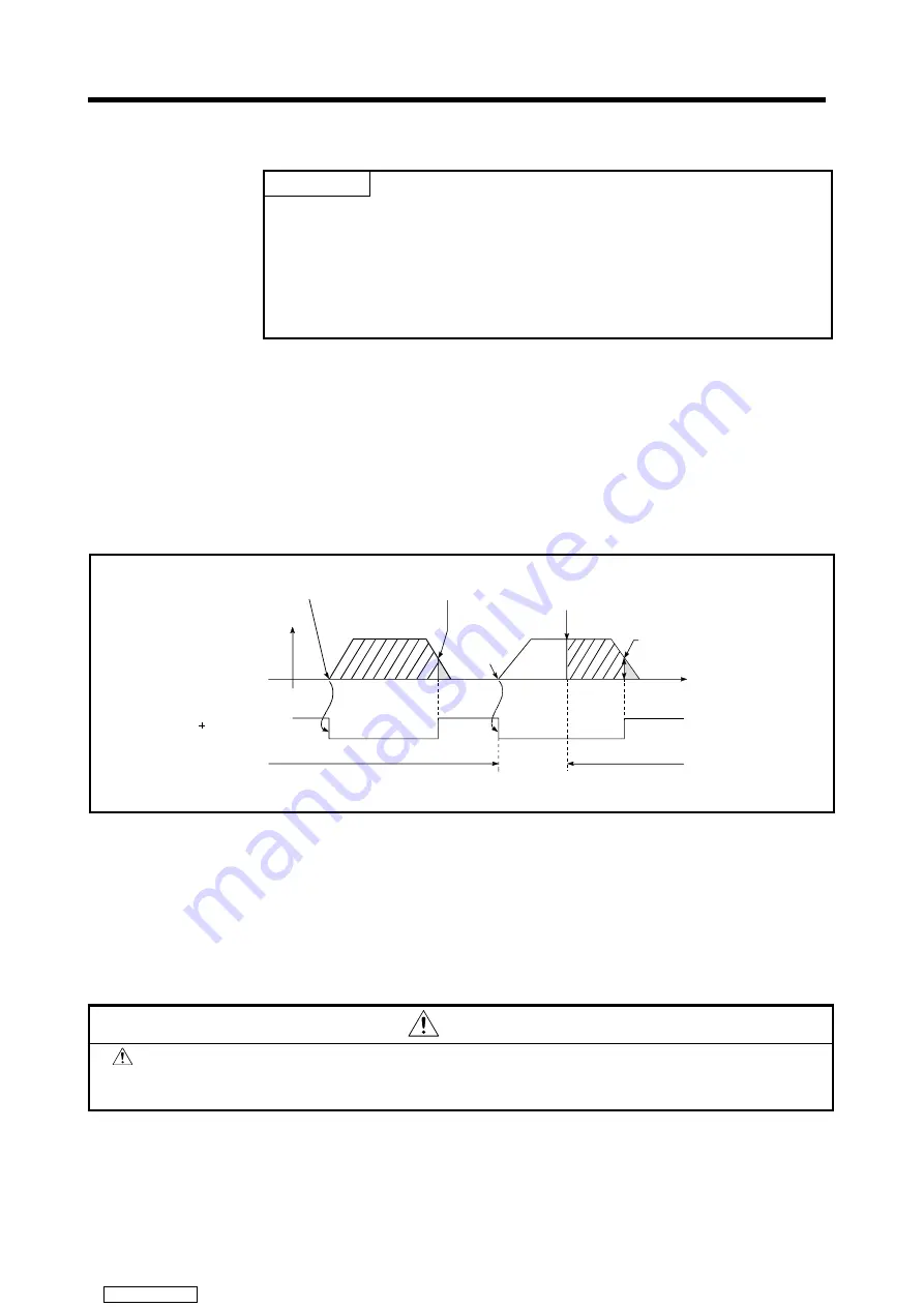
4.2.3
Command in-position range
The command in-position is the difference between the positioning address
(command position) and feed current value.
Once the value for the command in-position has been set, the command in-
position signal (M1603
+
20n) will come ON when the difference between the
command position and the feed current value enters the set range [(command
position
−
feed current value)
≤
(command in-position range)].
The command in-position range check is executed continuously during positioning
control.
Positioning
control start
Switch from
speed to
position
Speed/position
switching control
start
Execution of command
in-position check
Command in-position
(M1603 20n
Command
in-position set value
OFF
ON
v
t
Execution of command
in-position check
Command
in-position set value
4.3 Servo
Parameters
(1) The servo parameters are parameters set for each axis: their settings are data
fixed by the specifications of the controlled motors and data required to execute
servo control.
(2) The servo parameters are set with a peripheral device.
CAUTION
After setting the servo parameters at a peripheral device, execute a "RELATIVE CHECK" and
execute positioning control in the "NO ERROR" status. If there is an error, check the relevant
points indicated in this manual and reset it.
Downloaded from


