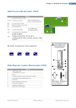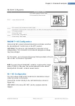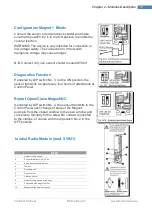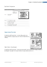
Installer Manual
Microvideo srl
www.microvideo.eu
9
Chapter 2 –Modules Description
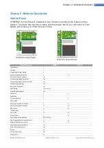
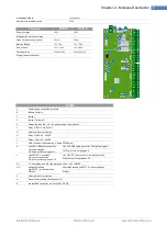
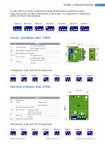
Section
Connector
SY810
RL3
NA,COM,NC
Free connectors of the relay 3
+12V
Power Connector 12V auxiliary
RL2
NA,COM,NC
Free terminals of Relay 2
GND
Power Supply Ground Connector
RL1
NA,COM,NC
Relay 1 Free connectors
AUX
OC1, OC2
Open Collector Connectors
OFF
Terminal State System
24h
24h Input
GND
Power Supply Ground Connector
ZONES
A8, A7, A6, A5
Input connectors of the 5-6-7-8 areas
+12V, GND
Auxiliary Power and Ground connectors
A4, A3, A2, A1
Input connectors of the 1-2-3-4 areas
+12V, GND
Auxiliary Power and Ground Connectors
BUS1
+V, H, L, GND
CAN Bus Connectors
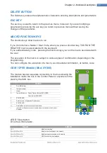
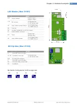
Keyboard (Mod. SY820)
SY820
A
Microphone capsule (Listening ambient)
B
Input Connector A1
C
Connector CAN Bus
D
speaker
E
USB connector (Programming, Log, Monitor Zone)
F
Exclusion Tamper Snatch
Closed: EXCLUDED tamper
Open: tamper ENABLED
Exclusion Tamper
Snatch Closed:
EXCLUDED tamper
Open: tamper
ENABLED
G
Snatch connector
H
Led Link USB On: USB
cable included
Off USB cable not
connected
Led Link USB On: USB
cable included
Off USB cable not
connected
I
Proximity key reader
SY820
A
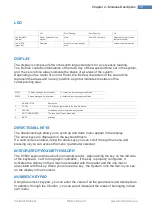
LED SIGNALS
B
LED Status System
C
Display
D
Arrow keys to scroll through the menus
E
Location Proximity Reader
F
Numeric keypad for entering the parameters
G
Ok button
H
Macro keys (F1, F2, F3, F4)
I
Function button to select F3 and F4 macro
J
DEL key
K
ESC key


