14
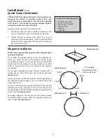
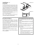
The Flowmeter must be installed in the boom supply line
after any strainers, return lines, or valves, but before the
boom shut-off valves. Se cure ly mount flow me ter (hardware
not supplied) in a vertical position in an area away from
in tense vibration. DO NOT install flowmeter closer than 12”
to the servo valve or the boom shut-off valves. (The flow-
me ter may need periodic cleaning, so it should be easy to
remove.) The flow meter is a bidirectional meter (exception:
Polmac’s 1 1/2”—3”). Liquid can flow in either direction, but
up is preferred. Make con nec tions us ing 3/4” fit tings without
the use of reducers, elbows or sharp bends for a minimum of
six inches (15 cm) either side of meter.
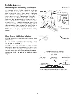
See Illustration 5.
NOTE: Save plastic plugs to protect flowmeter during
storage.
Illustration 5
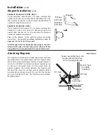
Flow Sensor Cable Installation
With the flowmeter in place, install the flow sensor cable
(GREEN body).
Screw sensor all the way into hole of flow me ter. Tight en 3/8”
jam nut to lock sen sor in place.
Uncoil flow sensor cable and carefully route it to meet the
main harness flow connector marked with GREEN tie. Align
connectors and press firmly together until locking tab clicks
into place. Secure cable with ties provided.
See Illustration 6.
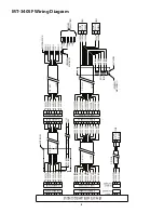
IMPORTANT NOTE: See page 8 for complete wiring
diagram.
5’ Hall-effect Flow Sensor Cable with
threaded sensor and male connector
(P/N 13096)
Connect flow sensor cable to green-tie console cable.
Green Body
Flow sensor
cable connector
Main harness
flow connector
Illustration 6
Green Tie
A B
C
C B A
Flow Sensor
Cable Connector
Main Harness
Flow Connector
Green Tie
Installation
(cont)
Mounting and Plumbing Flowmeter
Sprayer Line*
Locknut
Sensor
(green body)
Flowmeter
* NOT SUPPLIED
“L” Bracket*
Hose Clamps*
¾” NPT Male Fitting*
Hose Clamps*
Hose Clamps*
Содержание MT-3405 LR F
Страница 1: ...MT 3405 F LR AUTOMATIC RATE CONTROLLER REFERENCE MANUAL TM ...
Страница 33: ...33 Appendices ...


