25
Pre-Field Sys tem Checkout
Before beginning actual spraying, perform the following
“Pre-field” procedure to ensure that your valve settings,
nozzle selection and desired speed range will allow the
MT-3405 to provide the required application control. This
procedure should be repeated for each new nozzle se lec-
tion and/or application rate. By performing all of the steps
listed below, you set up your system to allow the MT-3405
to perform at optimum level. Fill your sprayer tank with
clean water.
DO NOT
use chemicals until the entire sys tem is
completely checked out and operating properly.
IMPORTANT NOTE: Most nozzles will maintain a good pattern
over a maximum speed range of two to one. (For example, if
your maximum speed is 12, your minimum speed shouldn’t
go below 6.)
NOTE: Pre-field System Checkout is a procedure performed
while the console is in the CAL mode. The Red WARNING
light will be lit during the procedure and “CAL” on the
display will be flashing.
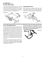
1. Completely open range adjust valve (if installed), ag i-
ta tion valve (if installed) and throttle valve (must be
installed).
NOTE: Pressure relief valve and diaphragm (positive
displacement) pump users should refer to Plumbing
Guidelines on page 37.
2. Start vehicle and pump, bring the engine up to normal
operating RPM.
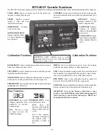
3. Enter MAXIMUM application TEST SPEED into con sole.
With console in HOLD, enter calibration mode. Push
and hold (CAL) buttons. CAL will appear on display and
red light will be on. Turn rotary switch to TEST SPEED
position. Use “+” or “-” button to enter maximum
application speed. Do not exit cal i bra tion mode. CAL will
flash indicating TEST SPEED preference mode.
4. Select manual “MAN” control mode, turn all boom
switches to ON position and put Run/Hold switch in RUN
position.
5. Turn rotary switch to APP. RATE position and hold “+”
button for approximately 30 seconds to completely
close the servo valve (control valve). (Minimum by pass
allowed - maximum flow output to booms.)
6. Adjust agitation valve for desired agitation. If range
valve is installed, adjust range valve until display reads
20% higher than the desired application rate.
CAN’T GET THERE?
If you can’t get to the desired ap pli ca tion rate, you may
need a different pump, or mod i fi ca tions to your plumbing
configuration. Please refer to Trou ble shoot ing Plumbing.
1. Slowly close the throttle valve until the display reads
slightly higher (5% to 10%) than the desired ap pli ca tion
rate. If the throttle valve is more than two-thirds closed,
install range valve and perform pre-field again.
2. Now is a good time to confirm that GPA, GPM, MPH,
WIDTH and PSI all coincide with the nozzle man u fac tur-
er’s charts. PSI may be slightly higher than indicated by
the charts due to pressure drop across the boom valves,
nozzle diaphragm check valves, nozzle screens, etc.
3. Enter MINIMUM application TEST SPEED into con sole.
Turn rotary switch to TEST SPEED position. Use the “+”
or “-” button to enter minimum application speed. Do
not exit calibration mode.
(Remember, the minimum
application speed is not normally less than half of the
maximum application speed.)
4. Put Run/Hold switch in RUN position (make certain
system is in Manual mode), turn rotary switch to APP.
RATE position and hold “-” button for approximately
30 seconds to completely open the servo valve (control
valve).
(Maximum bypass al lowed — min i mum flow
output to booms.)
The display should now read less than
the desired application rate.
5. It is not normally a problem if the application rate goes
all the way to zero when holding the “-” button for 30
sec onds, as long as it goes back up when the “+” but ton
is held.
CAN’T GET THERE?
If holding the “-” button does not get the application rate
to go below the desired ap pli ca tion rate, please refer to
Troubleshooting Plumbing.
1. Enter nominal application TEST SPEED into con sole. Put
the Run/Hold switch in HOLD. Turn rotary switch to TEST
SPEED position. Use the “+” or “-” button to enter target
application speed. Do not exit calibration mode.
2. Select automatic “AUTO” control mode, put Run/Hold
switch in RUN position and turn rotary switch to APP.
RATE position. The console should take control and
lock-on to your calibrated target application rate.
3. If you calibrated your ADJUST RATE to zero (.0), dis re gard
the next two steps.
4. Press the “+” button and release. The display will
momentarily show the new target rate (target rate +
ad just rate) and then lock on to that rate.
5. Press the “-” button and release. The display will mo men-
tari ly show the new target rate
(target rate - ad just rate)
and then lock on to that rate.
6. If the application rate was correctly displayed dur ing
man u al “MAN” control mode, but registered too high in
automatic “AUTO” control mode, the calibration val ue
for MIN FLOW is set too high.
At this point, the Pre-Field System Check-Out is complete.
TEST SPEED will automatically cancel when you exit the CAL
mode or when power to the console is turned OFF.
Содержание MT-3405 LR F
Страница 1: ...MT 3405 F LR AUTOMATIC RATE CONTROLLER REFERENCE MANUAL TM ...
Страница 33: ...33 Appendices ...

