12
EXAMPLE IN ENGLISH/TURF UNITS
If your revolution measurement is 97 inches, dividing that
number by 20 gives you a value of 4.85. Rounding 4.85 up to
the nearest even number is 6. For this example, the minimum
number of magnets required is 6.
EXAMPLE IN METRIC UNITS
If your revolution measurement is 2.5 meters, dividing that
number by .5 gives you a value of 5. Rounding 5 up to the
nearest even number is 6. For this example, the minimum
number of magnets required is 6.
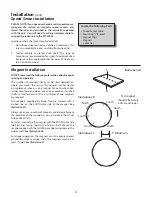
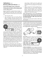
Refer to the diagram to the right for general mounting
instructions.
For specific mounting instructions, refer to
Appendix A in the back of this manual.
NOTE: Magnets may be attached mechanically as shown or
adhered with epoxy or other high quality adhesive. When
using adhesive, thoroughly clean the area of dirt and oil.
Attaching Magnets
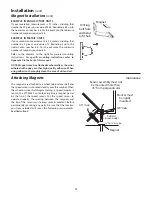
The magnets are attached to a wheel hub or drive shaft and
the speed sensor is mounted directly over the magnet. When
the wheel or drive shaft begins turning, a speed impulse is
sent to the MT-3405 F console every time a magnet passes
by the tip of the speed sensor. For the speed sensor to
operate properly, the spacing between the magnets and
the tip of the sensor must always remain constant. Before
permanently mounting any parts, be sure that the location
you have selected will meet the following requirements.
See Illustration 4.
Illustration 4
Installation
(cont)
Magnet Installation
(cont)
Drill lug
bolt hole
and bend
to fit hub
Magnet
45° max
Sensor
(Green body)
Magnet
3/8” nuts
Bracket must
be rigidly
mounted
Sensor assembly must not
be mounted more than
45° from perpendicular
¼” to ½” air gap
Содержание MT-3405 LR F
Страница 1: ...MT 3405 F LR AUTOMATIC RATE CONTROLLER REFERENCE MANUAL TM ...
Страница 33: ...33 Appendices ...


