21
Drive Shaft Speed Sensor Calibration
NOTE: If you have mounted the magnetic speed sen sor on
a wheel, skip this step and go on to Fine Tuning Speed/
Distance Calibration Values.
Because of the difference in wheel-to-drive shaft ra tios, it is
difficult to determine a calibration value for installation on
a drive shaft by measuring a wheel. You must start with an
estimated calibration value and then fine-tune the cal i bra-
tion.
1. Place the console in HOLD.
2. Press and hold the “CAL” key for three sec onds to
en ter the cal i bra tion mode. Turn the dial to “CIRC”
po si tion. The display will alternate between the wheel
circumference (CIRC) and dis tance values at about three-
sec ond intervals. (When the word “CAL” appears, the
num ber dis played is the wheel cir cum fer ence (CIRC)
value. When “CAL” does not appear, this is the dis tance
value.)
3. When the display shows wheel circumference (“CAL” is
displayed) , use the “+” or “-” key to adjust the displayed
value to any number be tween 10 and 15 (255mm to
380mm). When the num ber shown on the dis play
match es the de sired value, you have ar rived at the
estimated calibration val ue. Exit “CAL” by press ing and
holding the “CAL” key for three seconds.
NOTE: If you let go of the “+” and “-” keys while you are
ad just ing the CIRC value, the console will wait to make
sure you are finished. After 64 sec onds, the dis play will
start al ter nat ing be tween the wheel cir cum fer ence (CIRC)
and distance values again. Make sure you know which
value you are adjusting.
NOTE: For fine-tuning the wheel cir cum fer ence (CIRC) value,
turn to page 24.
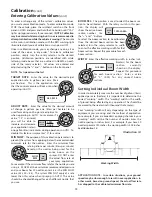
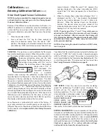
FLOW CAL:
This po si tion is used to cal i brate the flow me ter
for ac cu rate liquid mea sure ment. When this po si tion is se lect-
ed, the display will alternately show, every three seconds, the
flowmeter calibration value and the total
flow value. The flowmeter calibration value is
the number shown along with “CAL” on the
display. The total flow value is the number
shown when “CAL” IS
NOT displayed. The
flowmeter calibration
value is typical
ly
selected when entering the calibration number from the
tag attached to the flowmeter. Enter the calibration value
stamped on the tag attached to the flowmeter. The total
flow value is typ i cal ly selected when you are fine-tuning the
flowmeter cal i bra tion (please refer to Fine-Tuning Flow me ter
Cal i bra tion). To select either one of the values for calibration,
simply press the “+” or “-” button when the val ue you want to
select is being displayed. Once selected, the display will stop
al ter nat ing between the two figures for one minute to allow
you to make the appropriate ad just ment. After one minute
fol low ing your last adjustment to the value, or after you
move the rotary selector away from the FLOW CAL po si tion,
the display will alternate between the two values.
Every flowmeter is calibrated with water at the factory. If
your spray solution has a specific gravity or viscosity that is
different than water, flowmeter calibration should be done
for the specific solution
(please refer to Fine-Tuning Flow me ter
Calibration.)
FLOW
CAL
TOTAL FLOW
Your Micro-Trak flowmeter has been tested at the factory and
assigned a “FLOW CAL” value to make it operate properly
with the MT-3405 F console. This number is stamped on the
metal tag attached to the flowmeter.
See Illustration 18.
This
is a starting point only. The value must be fine tuned.
See
Fine-Tuning Flowmeter Calibration on page 25.
Illustration 18
Calibration
(cont)
Entering Calibration Values
(cont)
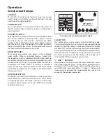
TEST SPEED:
Enter the value to be used for simulating
speed for perform
ing Pre-Field System Checkout. The
console will use this speed for simulating
spraying operations. The test speed value is
only used while in calibration mode. Once CAL
is exited, the Test Speed value is reset to zero.
DO NOT ENTER A TEST
SPEED UNTIL ALL
OTHER VALUES ARE
PROPERLY ADJUSTED.
Please refer to Pre-Field System Checkout for details.
TARGET
RATE
APP. RATE
EXITING CALIBRATION:
Upon completion of the cal i bra-
tion process, exit calibration by pressing and holding the CAL
button until the RED warning light turns off (ap prox i mate ly
three sec onds). Basic cal i bra tion is now com plete.
BEFORE
beginning application, confirm that the system is set up to
do the job that you want it to.
Please refer to Pre-Field System
Checkout on page 26—27 to confirm cal i bra tion settings,
nozzle selec tion and overall system per for mance.
Содержание MT-3405 LR F
Страница 1: ...MT 3405 F LR AUTOMATIC RATE CONTROLLER REFERENCE MANUAL TM ...
Страница 33: ...33 Appendices ...

