5
Table of Contents
(cont)
Troubleshooting
(cont)
.................................................................................................................................................... 29-34
Checking Individual Components ........................................................................................................................................30, 32-33
Console ...............................................................................................................................................................................................30
Harness ...............................................................................................................................................................................................30
Electrical
Interface ..........................................................................................................................................................................30
Power ..................................................................................................................................................................................................30
Accessory
Power .............................................................................................................................................................................30
Magnetic Hall-effect Speed and Flow Sensors ....................................................................................................................32
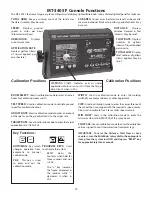
Console
Inputs .................................................................................................................................................................................32
Speed Input ..................................................................................................................................................................................32
Flow Input .....................................................................................................................................................................................32
Flowmeter .........................................................................................................................................................................................32
Boom
Valves .....................................................................................................................................................................................33
Servo Valve Control Signal ..........................................................................................................................................................33
Servo
Valve ........................................................................................................................................................................................33
Plumbing ...........................................................................................................................................................................................33
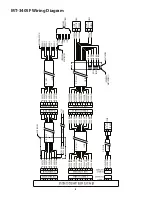
MT-3405 F Wiring Diagram ................................................................................................................................................... 31
Flowmeter Assembly .............................................................................................................................................................. 35
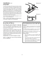
Plumbing Guidelines ........................................................................................................................................................ 36-37
General ........................................................................................................................................................................................................36
Pump Inlet ..................................................................................................................................................................................................36
Agitation .....................................................................................................................................................................................................36
Servo ............................................................................................................................................................................................................36
Flowmeter ..................................................................................................................................................................................................36
Pump ............................................................................................................................................................................................................36
Valve Purpose and Adjustments ..................................................................................................................................................36-37
Tank Shut-off Valve .................................................................................................................................................................................36
Agitation Shut-off Valve ........................................................................................................................................................................36
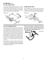
Pressure Relief Valve...............................................................................................................................................................................37
Range Adjust Valve .................................................................................................................................................................................37
Throttle Valve ............................................................................................................................................................................................37
Relief Valve .................................................................................................................................................................................................37
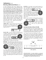
12-Volt Servo Valve Calibration ..........................................................................................................................................................38
Appendices ......................................................................................................................................................................... 39-45
Appendix A: Optional Speed Sensor Mounting Installation .............................................................................................39-41
Appendix B: Various Ball Valve Configurations ............................................................................................................................42
Appendix C: Conversion Chart ...........................................................................................................................................................43
Appendix D: Replacement Parts ........................................................................................................................................................44
Appendix E: Wiring Diagram for Non-Bulkhead Systems ........................................................................................................45
Notes ...............................................................................................................................................................................................
Содержание MT-3405 LR F
Страница 1: ...MT 3405 F LR AUTOMATIC RATE CONTROLLER REFERENCE MANUAL TM ...
Страница 33: ...33 Appendices ...


