Meyer LPV 3 Скачать руководство пользователя страница 60

60

61

Maintenance

Inspection:

 Before and after each use, spreader should be 

inspected for loose, missing, or damaged mounting hardware, 

parts, or safety guards. Spreader should also be inspected to 

ensure it is securely attached to vehicle.

Cleaning:

 Empty all material from spreader after each snow 

or ice event. Wash entire spreader with soap and warm water 

paying special attention to the conveyor drag chain. Do not 

clean spreader with any corrosive chemicals or products that 

contain chlorides or ammonium. Any commercially available 

salt neutralizer may be applied.

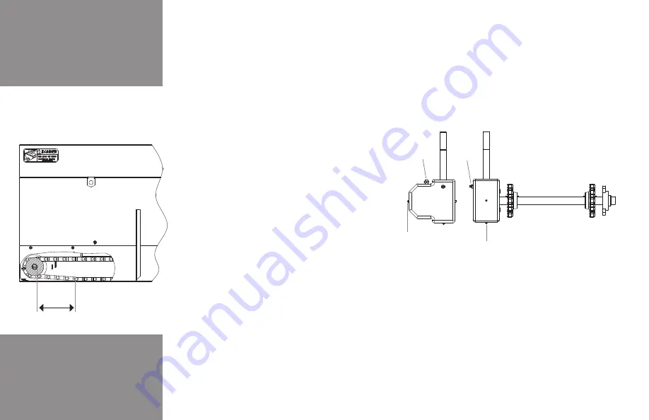
Adjusting Drag Chain Tension:

 Loosen rear jam nut on 

take-up bolt and tighten take-up bolt until drag chain is 

properly tensioned. Drag chain is properly tensioned when 

the distance between the centerline of the front idler and 

point where chain contacts flange of longitudinal is between 


 ( .     . cm).  oth sides of drag chain must be 

adjusted evenly.

Adjusting V-belt/ Roller Chain Tension:

 Loosen the gasoline 

engine or electric motor mounting bolts and slide motor away 

from gearbo  (towards passenger side of vehicle) until proper 

tension is achieved. Tighten motor mounting bolts to hold motor 

in position. V-belt or roller chain should have between 1/4"– 5/16" 

(.  cm  .  cm) de ection midway between the sprockets.

Adjusting Spinner Roller Chain:

 Loosen four spinner shaft 

or spinner drive shaft ( olyhawk models only) mounting bolts 

and slide shaft away from gearbo  (towards passenger side 

of 

vehicle) until proper tension is achieved and shaft is straight 

up and down, then tighten shaft mounting bolts to hold shaft 

in position. Roller chain should have between 1/4" – 5/16" 

deflection midway between sprockets. To prevent roller chain 

failure, both sprockets must be realigned. For  olyhawk 

models spinner shaft may need to be aligned with the spinner 

drive shaft after adjusting roller chain tension.

Gearbox Oil Level:


Check the gearbo  oil level every   

hours of operation or monthly. Gearbox should be filled until 

oil reaches oil level plug. Oil should be flushed prior to start of 

season and replaced with an     W 

 gear type lubricant.

Electrical System: 

Electrical system should be inspected for 

loose connections and corrosion every   hours of operation 

or weekly. Dielectric grease should be applied to all electrical 

connections.

General Maintenance

Gearbox Maintenance

Breather

Grease 

Zerk

Drain Plug

Oil Level Plug

Drag Chain Tension 

Adjustment

8.0"– 20.0"

(20.3cm – 50.8cm)

Maintenance

Gearbox

Input Shaft

Bearing

Bearings

Bearings

Lubrication

Transmitter Battery 

Replacement

Lubrication:

 After every   hours of operation or weekly, 

lubricate drag chain and roller chains with any commercial chain 

lubricant or a mi ture of 

 motor oil   

 diesel fuel. After 

every   hours of operation or weekly, lubricate drive shaft, 

spinner drive shaft and spinner shaft bearings with high quality 

chassis grease. After every   hours of operation or monthly, 

lubricate gearbox input shaft bearing with high quality chassis 

grease. 

CAUTION: 

over greasing gearbox input shaft bearing 

will result in damage to the gearbox input shaft seal.

Wireless Remote Transmitter Battery Replacement:


Wireless controller transmitter battery should be replaced before 

the start of each season. It is also recommended to keep a spare 

battery with the vehicle. Wireless transmitter requires a standard 

CR

 lithium button cell battery.

1.

  Gently press and slide off the battery cover from the   

  wireless transmitter.

2.

  Remove the battery by sliding it out from underneath the  

  retainer. Do not attempt to remove the battery by lifting it  

  up from the retainer.

3.

  Install new battery by sliding it under the retainer. Battery  

  must be installed with the positive ( ) symbol visible.

Electric Clutch:

 The electric clutch on new spreaders and re-

placement clutches should be burnished before use to achieve 

maximum torque. The clutch burnishing procedure is as follows:

1.

  Idle Engine

2.

  ngage clutch for   seconds

3.

  Disengage clutch for   seconds

4.

  Repeat steps      , 

 times to achieve ma imum  

  clutch torque.

At the end of the winter season remove the electric clutch, add a 

coat of light oil to each mating half and store indoors to prevent 

corrosion. Prior to start of next season, oil should be removed 

and clutch should be reassembled onto spreader.

Gasoline Engine:

 Follow engine manufacturer s maintenance 

recommendations.

Содержание LPV 3

Страница 1: ...finitions Warnings 3 11 Spreader Component Identification LPV Spreader 6 7 PV Spreader 12 13 Polyhawk 14 15 Controller Operation Trouble Shooting LPV Spreader 6 7 PV Spreader 12 13 Polyhawk 14 15 Gene...

Страница 2: ...Y VEHICLE WITH A SPREADERWITHOUTCONSULTINGVEHICLE MANUFACTURERS RECOMMENDATIONS Vehicles equipped with Meyer spreaders installed may be so equipped as to meet vehicle manufacturers specifications and...

Страница 3: ...neral safety procedures when operating moving storing cleaning or servicing this equipment CAUTION Empty Hopper This decal cautions all to only lift or move equipment when hopper is empty to prevent t...

Страница 4: ...cecertificationlabelonthedriver ssidedooropening Failuretocomplywillresultindeathor seriousinjury 12 Spreadermaytipoverorfall Spreadershouldbesolidlysupportedwhenbeingmounted dismounted moved orstored...

Страница 5: ...Therefore donotallowflames sparksorlittobaccotocomenearthebattery Whenchargingorworkingnearabattery alwayscoveryourfaceandprotectyoureyes andalsoprovideventilation Batteriescontainsulfuricacidwhich bu...

Страница 6: ...6 Safety Decal Locations These safety alert decals are used to alert you of potential personal injury hazards Obey all safety messages that follow the symbol to avoid possible injury or death...

Страница 7: ...ting all power sources DANGER Spinner Alerts all to the danger of any person being near the spinner while it is turning where serious personal injury could result if struck by flying debris CAUTION Ca...

Страница 8: ...erve general safety procedures when operating moving storing cleaning or servicing this equipment CAUTION Empty Hopper decal cautions all to only lift or move equipment when hopper is empty to prevent...

Страница 9: ...e spinner while it is turning where serious personal injury could result if struck by flying debris CAUTION decal cautions all to observe general safety procedures when operating moving storing cleani...

Страница 10: ...10 Safety Guards To prevent serious personal injury of death all safety guards covers must be securely fastened in proper location while equipment is operating or capable of being operated...

Страница 11: ...11 LPV Safety Guards Top Screen Sprocket Cover Engine Motor Cover Spinner Assembly Bearing Cover Sprocket Cover Idler Guard Front Conveyor Cover Screen Lock...

Страница 12: ...12 PV Safety Guards Top Screen Engine Motor Cover Spinner Assembly External Baffles Bearing Cover Idler Guard Front Conveyor Cover...

Страница 13: ...13 Polyhawk Safety Guards Top Screen Front Conveyor Cover Idler Guard Sprocket Cover External Baffles Spinner Assembly Rear Conveyor Cover Engine Motor Cover Bearing Cover...

Страница 14: ...14 1 2 3 4 5 6 7 8 9 10 11 12 13 14 15 LPV Component Identification GASOLINE ENGINE...

Страница 15: ...earbox Assembly ratio gearbo receives power from the motor and moves drag chain 9 Drag Chain Is driven by the gearbox and moves material out of hopper to the spinner assembly 10 Gasoline Engine Suppli...

Страница 16: ...16 ELECTRIC LPV Component Identification 1 2 3 4 5 6 7 8 9 10 11 12 13 14 15...

Страница 17: ...plies tension to the drag chain 8 Gearbox Assembly ratio gearbo receives power from the motor and moves drag chain 9 Drag Chain Is driven by the gearbox and moves material out of hopper to the spinner...

Страница 18: ...18 PV Spreader Component Identification 1 2 3 4 5 6 7 8 9 10 11 12 13 14 15 16 17 18 GASOLINE ENGINE...

Страница 19: ...Idler Assembly Applies tension to the drag chain 10 Gearbox Assembly ratio gearbo receives power from the motor and moves drag chain 11 Drag Chain Is driven by the gearbox and moves material out of ho...

Страница 20: ...20 PV Spreader Component Identification ELECTRIC 1 2 3 4 5 6 7 8 9 10 11 12 13 14 15 16 17 18...

Страница 21: ...ates amount of material being discharged from the conveyor 9 Idler Assembly Applies tension to the drag chain 10 Gearbox Assembly ratio gearbo receives power from the motor and moves drag chain 11 Dra...

Страница 22: ...22 PV Spreader Component Identification HYDRAULIC 1 2 3 4 5 6 7 8 9 10 11 12 13 14 15 16 17 18 19...

Страница 23: ...he conveyor 9 Idler Assembly Applies tension to the drag chain 10 Gearbox Assembly ratio gearbo receives power from the motor and moves drag chain 11 Drag Chain Is driven by the gearbox and moves mate...

Страница 24: ...24 GAS ENGINE Polyhawk Component Identification 1 2 3 4 5 6 8 9 10 11 12 13 14 15 16 17 18 19 7...

Страница 25: ...g hopper 9 Feedgate Regulates amount of material being discharged from conveyor 10 Idler Assembly Applies tension to the drag chain 11 Gearbox ratio gearbo received power from the motor and moves drag...

Страница 26: ...26 ELECTRIC Polyhawk Component Identification 1 2 3 4 5 6 8 9 10 11 12 7 13 14 15 16 17 18 19...

Страница 27: ...ts form entering hopper 9 Feedgate Regulates amount of material being discharged from the conveyor 10 Idler Assembly Applies tension to the drag chain 11 Gearbox Assembly ratio gearbo received power f...

Страница 28: ...28 1 2 3 4 5 6 8 9 10 11 12 HYDRAULIC Polyhawk Component Identification 7 13 14 15 16 17 18 19 20...

Страница 29: ...t of material being discharged from conveyor 10 Idler Assembly Applies tension to the drag chain 11 Gearbox Assembly gear reduction receives power from engine and contains drive shaft which moves drag...

Страница 30: ...l trucks buses and multipurpose passenger vehicles manufactured on or after 5 1 1993 with a gross vehicle weight rating WR of LBS or less and an overall width less than be e uipped with a center high...

Страница 31: ...corner of spreader at opposing angles Eye bolt or standard cargo tiedown point 1 2 hardware to be installed through each body jack and the vehicle bed Installation Assembly Instructions SHOULD THERE B...

Страница 32: ...32 LPV Installation Assembly Instructions Lifting Location Crane only Tiedown Location each corner Bolt Location each body jack LIFTING TIEDOWN LOCATIONS...

Страница 33: ...be removed before mounting spreader Verify mounting method is acceptable to vehicle manufacturer before attempting to mount spreader 1 Place spreader directly onto bed of vehicle with discharge at th...

Страница 34: ...34 LPV Installation Assembly Instructions Supplied hardware to be installed in six locations SPINNER INSTALLATION...

Страница 35: ...llation Assembly Instructions Spinner Assembly Installation Spinner should be solidly supported during installation Spinner assembly weighs over lbs kg and may require more than one person for safe in...

Страница 36: ...36 PV Installation Assembly Instructions Lifting Location crane only Lifting Location forklift only Tiedown Location each corner Bolt Location each body jack LIFTING TIEDOWN LOCATIONS...

Страница 37: ...reader should be mounted directly on vehicle bed spreader is not designed to be supported by body jacks alone or for chassis mount applications Shipping skid is intended to be removed before mounting...

Страница 38: ...38 PV Installation Assembly Instructions Supplied hardware to be installed in six locations SPINNER INSTALLATION FPO...

Страница 39: ...ns 3 Caution Spreader may be shipped without oil in the gear bo Fill gearbo to oil level plug with an W gear type lubricant 4 Add fuel to engine fuel tank refer to engine manufacturers instructions 5...

Страница 40: ...hawk series spreader will mount on most medium or heavy duty pickup trucks Polyhawk series spreaders can be mounted on 1 ton and larger trucks but may require optional spinner extension Lifting Locati...

Страница 41: ...lift is of an adequate weight rating to prevent forklift from tipping while moving spreader Spreader Installation The Polyhawk series spreader should be mounted directly on vehicle bed spreader is not...

Страница 42: ...42 SPINNER INSTALLATION Polyhawk Installation Assembly Instructions Rear Slots Front Slots Handle Rear Holes Front Pipe Spinner Rods...

Страница 43: ...uctions 3 Caution Spreader may be shipped without oil in the gearbox Fill gearbo to oil level plug with W gear type lubricant 4 Add fuel to engine fuel tank refer to engine manufacturers instructions...

Страница 44: ...ove the ON OFF switch up to the ON position 2 Set engine throttle to choke by pressing and holding the THROTT TTON up for two seconds 3 ress and hold the START CON OR button in the up position until t...

Страница 45: ...button after the engine starts will result in damage to the engine 3 Once engine starts press the throttle D CR AS button to remove throttle from the choke position 4 ress the throttle INCR AS or thr...

Страница 46: ...full speed NOT depending upon the weight of material on the conveyor or spinner electric motors may not operate at lower dial settings BLAST FEATURE Controller is also equipped with a blast feature Th...

Страница 47: ...the motor at full speed until deactivated Blast feature can be deactivated at any time and controller will return to previous speed setting y pressing the OFF button on the transmitter controller and...

Страница 48: ...all spreader functions are operating correctly and replace base receiver cover If programming was unsuccessful repeat pro gramming procedure or see trouble shooting guide in this manual Variable Spee...

Страница 49: ...ain the ross ehicle Weight W 5 Obtain ross ehicle Weight Rating WR Front ross A le Weight Rating F AWR and Rear ross A le Weight Rating R AWR from the drivers door am or from the vehicle manufacturer...

Страница 50: ...7 Coarse Sand Wet 1 472 Volume at Specified Height Cu Yds Spreader Full LPV 3 LPV 4 LPV 5 LPV 6 LPV 7 LPV 8 Spreader Full PV 5 PV 6 PV 7 PV 8 PV 9 1 22 1 36 Polyhawk Volume at Specified Height M3 Spre...

Страница 51: ...To achieve maximum torque new elec tric clutches should be burnished prior to the first use Refer to the maintenance section of this manual for clutch burnishing procedure Transporting Spreader It is...

Страница 52: ...pinner hydraulic motor Operating Instructions DESIRED SPREAD PATTERN BAFFLE SETTING INTERNAL EXTERNAL LEFT RIGHT LH UP LH UP CENTER UP RH UP RH UP LEFT LH UP LH UP CENTER UP RH DOWN RH DOWN RIGHT LH D...

Страница 53: ...53 Operating Instructions Left Right Pattern Left Spread Pattern Right Spread Pattern WindRow Spread Pattern...

Страница 54: ...matic for spreaders with Briggs Stratton engine and wired controller Connect to Engine Kill Wire Connect to Throttle Actuator Brown Black Green 15 A Fuse Red Red 12V from Vehicle Yellow Blue Red Start...

Страница 55: ...and wireless controller Connect to Throttle Actuator Connect to Engine Kill Wire Black Green 15 A Fuse Red White Starter Solenoid Starter Wire Yellow Blue Capacitor Brown Battery Cable Red Wireless Re...

Страница 56: ...rical Hydraulic Schematics Wiring schematic for electric spreaders with wireless variable speed controllers Wireless Receiver Conveyor Motor 12V from Vehicle Green Red Red Red Red Black Black Circuit...

Страница 57: ...tics Wiring schematic for electric spreaders with dual variable speed controllers 12V from Vehicle Red Black Black Red Conveyor Motor Black Terminal Red Terminal Black Red Spinner Motor Black Black Re...

Страница 58: ...ydraulic Schematics Plumbing schematic for hydraulic spreaders Conveyor Motor Single flow controller plumbing Dual flow controller plumbing Conveyor Motor Spinner Motor Spinner Motor Pressure Pressure...

Страница 59: ...hicle supporting the spreader must be properly serviced The system should consist of at least a amp hr battery and a amp alternator e sure to check regularly 1 Battery terminals to assure they re tigh...

Страница 60: ...d Tighten motor mounting bolts to hold motor in position V belt or roller chain should have between 1 4 5 16 cm cm de ection midway between the sprockets Adjusting Spinner Roller Chain Loosen four spi...

Страница 61: ...icle Wireless transmitter requires a standard CR lithium button cell battery 1 Gently press and slide off the battery cover from the wireless transmitter 2 Remove the battery by sliding it out from un...

Страница 62: ...nthly Post Season Inspect spreader for loose missing or damaged parts or hardware X X X Verify spreader is securely attached to vehicle X X Inspect electrical connections and apply dielectric grease t...

Страница 63: ...g properly See electric clutch troubleshooting Loose or damaged v belt or roller chain Ad ust or replace v belt or roller chain Loose or damaged drag chain Ad ust or replace drag chain Worn drive spro...

Страница 64: ...e chute Conveyor discharge clogged Clear material from discharge Material bridging inside hopper Use free flowing material Feed gate closed Open feed gate Inverted Vee not installed Install inverted V...

Страница 65: ...eader battery Fuse is blown Replace fuse in spreader control cable Spreader control cable ground white wire is loose or corroded Clean and tighten connection Receiver is defective See receiver trouble...

Страница 66: ...only be operated one at a time within the same area Receiver does not function Transmitter is defective See transmitter troubleshooting Transmitter is not programmed to the receiver See programming i...

Страница 67: ...r setting Controller internal fuse blown Replace fuse Conveyor harness damaged Replace conveyor harness Controller has power but spinner does not operate Spinner harness is not connected to controller...

Страница 68: ...lutch Replace clutch Fuse blown Replace fuse Loose wire connection or ground Repair and clean loose connection Wireless controller not functioning properly See wireless controller troubleshooting V be...

Страница 69: ...n Insufficient pump speed Increase PTO RPM accordingly Erratic operation of conveyor and or spinner motor Low oil Fill reservoir to full Worn or defective motor Repair or replace motor Dirty worn or d...

Страница 70: ...For the address and telephone number of the Distributor Sub Distributor nearest you check the telephone directory or you may write to Meyer Products at the address below General It is the responsibil...

Страница 71: ...71 Notes...

Страница 72: ...72...

Отзывы: