AUTOMATIC TRANSAXLE
OIL COOLER FLUSHING
Note
• The contaminated cooler line (oil pipes and
hoses) and auxiliary cooler (if equipped) must
be flushed completely when ATX is overhauled
or replaced.
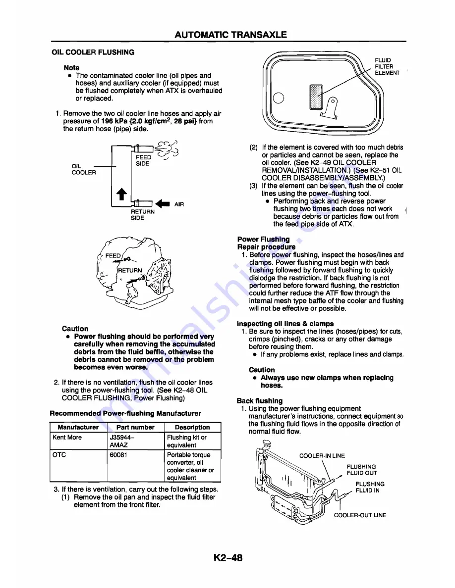
1. Remove the two oil cooler line hoses and apply air
pressure of
196 kPa {2.0 kgf/cm2, 28 psi}
from
the return hose (pipe) side.
o i l
—
CO O LE R
FEED
S ID E
AIR
RETURN
S ID E
Caution
• Power flushing should be performed very
carefully when removing the accumulated
debris from the fluid baffle, otherwise the
debris cannot be removed or the problem
becomes even worse.
2. If there is no ventilation, flush the oil cooler lines
using the power-flushing tool. (See K2-48 OIL
COOLER FLUSHING, Power Flushing)
Recommended Power-flushing Manufacturer
Manufacturer
Part number
Description
Kent More
J35944-
AMAZ
Flushing kit or
equivalent
OTC
60081
Portable torque
converter, oil
cooler cleaner or
equivalent
3. If there is ventilation, carry out the following steps.
(1 ) Remove the oil pan and inspect the fluid filter
element from the front filter.
(2) If the element is covered with too much debris
or particles and cannot be seen, replace the
oil cooler. (See K2-49 OIL COOLER
REMOVAL/INSTALLATION.) (See K2-51 OIL
COOLER DISASSEMBLY/ASSEMBLY.)
(3) If the element can be seen, flush the oil cooler
lines using the power-flushing tool.
• Performing back and reverse power
flushing two times each does not work
|
because debris or particles flow out from
the feed pipe side of ATX.
Power Flushing
Repair procedure
1. Before power flushing, inspect the hoses/lines and
clamps. Power flushing must begin with back
flushing followed by forward flushing to quickly
dislodge the restriction. If back flushing is not
performed before forward flushing, the restriction
could further reduce the ATF flow through the
internal mesh type baffle of the cooler and flushing
will not be effective or possible.
Inspecting oil lines & clamps
1. Be sure to inspect the lines (hoses/pipes) for cuts,
crimps (pinched), cracks or any other damage
before reusing them.
• If any problems exist, replace lines and clamps.
Caution
• Always use new clamps when replacing
hoses.
Back flushing
1. Using the power flushing equipment
manufacturer’s instructions, connect equipment so
the flushing fluid flows in the opposite direction of
normal fluid flow.
K 2-48
Содержание 626 Station Wagon
Страница 25: ...CONTROL SYSTEM WIRING DIAGRAM With Immobilizer System OUTLINE F1 4 ...
Страница 179: ...OUTLINE SYSTEM WIRING DIAGRAM S m ç g fT I C g 3 3 21 A m Hi p È a t ï S 3 M h d 0H ÜB 1 Hl J e F2 3 ...
Страница 183: ...CONTROL SYSTEM COMPONENT LOCATION F2 7 ...
Страница 204: ...MANUAL TRANSAXLE FEATURES OUTLINE J 2 OUTLINE OF CONSTRUCTION J 2 SPECIFICATIONS J 2 D J 1 ...
Страница 206: ...AUTOMATIC TRANSAXLE GF4A EL FEATURES OUTLINE K1 2 OUTLINE OF CONSTRUCTION K 1 2 SPECIFICATION K1 2 K1 1 ...
Страница 266: ...SHIFT MECHANISM 6 Apply grease to the cam as shown K2 59 ...
Страница 418: ...TROUBLESHOOTING KEYLESS ENTRY SYSTEM ON BOARD DIAGNOSTIC FUNCTION S 37 ...
Страница 454: ...WARNING AND INDICATOR SYSTEM O p e ra tin g O rd e r T 32 ...


