


F5 3D Imaging System User Manual
95
2
Select the
icon from the Measurement toolbar.
3
Define a plane using the Plane toolbar options (refer to the Defining a Snap
Plane Using Point Sets section on page 81 and the Defining a Snap Plane Using
an Existing Plane section on page 83.
– OR –
Select a previously defined plane by double-clicking the plane in the Primitives
pane, and then press Enter.
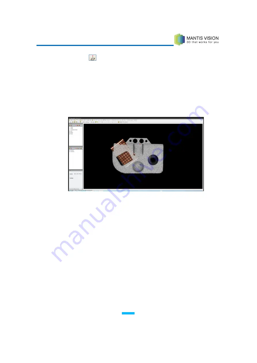
Figure 90: Defining a Plane for a Point Plane Measurement
4
Double-click a point not on the plane by double-clicking repeatedly until the
preferred point is selected.
– OR –
Instead of defining a new point, select a previously defined point in the
Primitives pane.
5
The (perpendicular) distance from the defined plane is displayed in the Main
Viewing window and in the Information pane.
When necessary, the application automatically extends the plane to ensure
that the line from the measured point intersects with the plane at a correct
angle.
Содержание F5-B
Страница 71: ...F5 3D Imaging System User Manual 71 Figure 58 Stitching Window and Side Panel Segment Tab ...
Страница 116: ...F5 3D Imaging System User Manual 116 Figure 109 KaplaVision Desktop Icon ...
Страница 119: ...F5 3D Imaging System User Manual 119 Figure 112 Calibration Camera Calibration Wall EPI Calibration page 123 ...
Страница 120: ...F5 3D Imaging System User Manual 120 Figure 113 Calibration EPI Calibration RIG Calibration page 123 ...
Страница 125: ...F5 3D Imaging System User Manual 125 Blank page for double sided printing ...


