F5 3D Imaging System User Manual
90
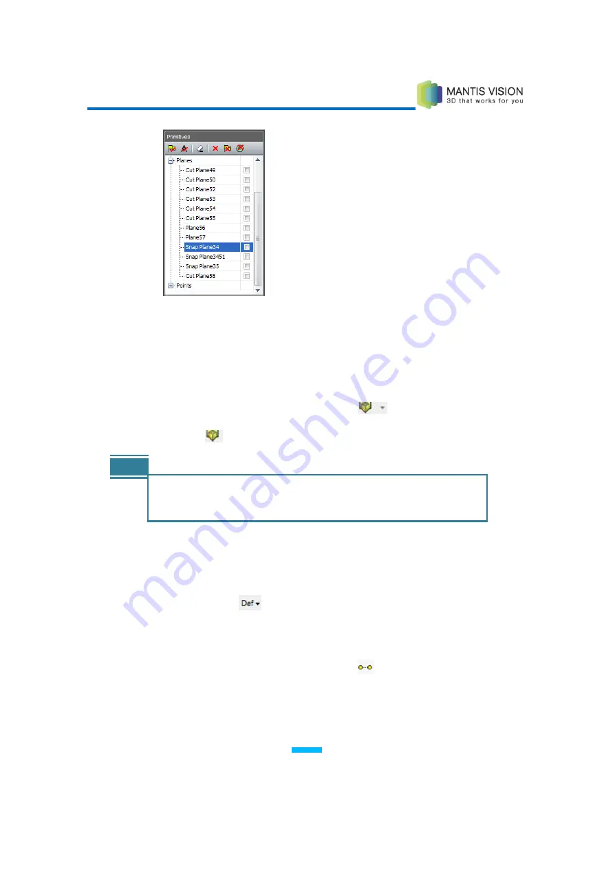
Figure 85: Selecting the Plane in the Primitives Pane
6
Press Enter to define the second plane. The new cut plane is defined and
displayed in the Main Viewing Area, and all points behind it are hidden. The
entry is recorded in the Primitives Plane.
7
To flip the cut plane so that all points in front of the plane are hidden, select
the Flip Cut Plane option in the Cut Plane
dropdown list.
8
Click the
icon to toggle the cut plane view on and off.
NOTE
You can combine the two options described in the preceding sections.
For example, you can create one plane by points and the second plane
using a previously defined plane.
Defining a Snap Line by Two Points
►
To define a snap line by two points:
1
Click the Define
button and select Define Snap Line. If creating a
free-form, non-snap line for a measurement, skip this step and begin with
step
2
.
2
Select the Choose Line by 2 Points option
on the Line toolbar to define the
relevant line.
3
Double-click a point in the scene (the line’s start point).
Содержание F5-B
Страница 71: ...F5 3D Imaging System User Manual 71 Figure 58 Stitching Window and Side Panel Segment Tab ...
Страница 116: ...F5 3D Imaging System User Manual 116 Figure 109 KaplaVision Desktop Icon ...
Страница 119: ...F5 3D Imaging System User Manual 119 Figure 112 Calibration Camera Calibration Wall EPI Calibration page 123 ...
Страница 120: ...F5 3D Imaging System User Manual 120 Figure 113 Calibration EPI Calibration RIG Calibration page 123 ...
Страница 125: ...F5 3D Imaging System User Manual 125 Blank page for double sided printing ...


