11
BA023001-en
The range spring now bends according to the torque generated by the motor. An
applied strain gauge converts the mechanical deformation of the range spring into
electrical signals, which can be converted into a braking torque in the control system
and visualized via a display unit.
The sensing roller directly measures the wheel speed. The magnitude of the slip can be
determined by comparing the drive speed with the sensing roller speed
–
both values
determined via sensors. To avoid unnecessary tyre wear, MAHA test benches switch
off automatically when the (legally) specified maximum slip is reached.
2.2.3
Intended use
•
This test bench is used exclusively for testing the braking efficiency of motor vehi-
cles. The permitted axle load must be observed.
•
The test bench must not be modified without express written permission from the
manufacturer. Non-compliance invalidates the declaration of conformity.
•
The operator must carry out a workplace hazard assessment for the test bench in-
cluding the available options.
•
The test bench must not be set up in explosion and fire hazard areas and in damp
rooms (e.g. washing halls).
•
The test bench is suitable for the temperature range 5...40 °C, for a maximum hu-
midity of 50 % (at 40 °C) and for an altitude of up to 1000 m above mean sea level.
•
Depending on the equipment, the test bench can also be set up outdoors. Prior
consultation necessary.
2.2.4
Brake test of vehicles with
one
driven axle
The vehicle is driven into the roller set with the axle to be tested. At the same time,
the two sensing rollers that measure the wheel speed are pressed down. A warning
message is issued and after approx. 3 seconds the two drive motors of the roller set
are started so that both vehicle wheels turn in the forward direction.
As soon as the nominal speed is reached, th
e “Ready for braking” LED lights up or the
corresponding user message appears on the respective display unit.
This signals that
the inspector can begin the braking process. To test the brakes, increase the force on
the brake pedal or parking brake lever quickly but not jerkily. In conjunction with an
electronic parking brake, this must be checked in accordance with the manufacturer's
specifications, usually by pressing the control button for the electronic parking brake
several times in quick succession.
Braking should only be applied until the required deceleration for the vehicle is
reached, braking up to slip cut-off is not mandatory. In this way, unnecessary tyre wear
can be avoided.
During the braking process, the speed of the drive roller and the sensing roller is
constantly compared. If braking is so severe that at least one sensing roller exceeds the
maximum permitted slip (e.g. 27 % slip), the drive motors are automatically switched
off. This serves both to protect the drive motors from overload and to protect the tyres
Содержание CONNECT Series
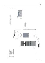
Страница 19: ...19 BA023001 en 2 3 2 Set up diagram Set up diagram I ...
Страница 20: ...20 BA023001 en Set up diagram II ...
Страница 22: ...22 BA023001 en 2 4 1 Wiring diagram ...
Страница 23: ...23 BA023001 en 2 4 2 Control cabinet structure Basic variant ...
Страница 24: ...24 BA023001 en 2 4 3 Control cabinet structure Full equipment ...
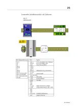
Страница 25: ...25 BA023001 en ...
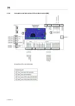
Страница 26: ...26 BA023001 en 2 4 4 Connection and termination of the central module ZM Connection of the central module ...
Страница 53: ...53 BA023001 en ...
Страница 138: ...138 BA023001 en 13 Annex 13 1 Naming convention ...


