118
BA023001-en
11.3.6
Setup
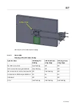
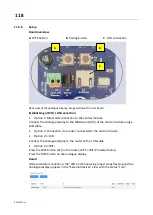
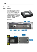
Board overview
A
WPS button
B
Pairing button
C
LAN connection
Rear view of the analogue display, image detail with circuit board
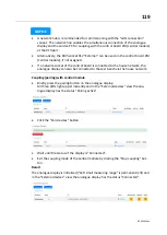
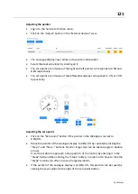
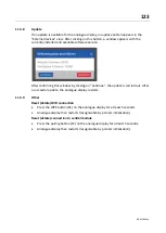
Establishing a WiFi / LAN connection
•
Option 1: Direct LAN connection to the central module
Connect the analogue display to the MAHA port (X13) of the central module using a
LAN cable.
•
Option 2: Connection via a router connected to the central module
•
Option 2.1: LAN
Connect the analogue display to the router with a LAN cable.
•
Option 2.2: WiFi
Press the WPS button (S1) on the router; WPS = WiFi Protected Setup.
Press the WPS button on the analogue display.
Result
After successful connection, the "LED small measuring range" stops flashing and the
analogue display appears in the "External devices" view with the status "Free".
A
B
C
Содержание CONNECT Series
Страница 19: ...19 BA023001 en 2 3 2 Set up diagram Set up diagram I ...
Страница 20: ...20 BA023001 en Set up diagram II ...
Страница 22: ...22 BA023001 en 2 4 1 Wiring diagram ...
Страница 23: ...23 BA023001 en 2 4 2 Control cabinet structure Basic variant ...
Страница 24: ...24 BA023001 en 2 4 3 Control cabinet structure Full equipment ...
Страница 25: ...25 BA023001 en ...
Страница 26: ...26 BA023001 en 2 4 4 Connection and termination of the central module ZM Connection of the central module ...
Страница 53: ...53 BA023001 en ...
Страница 138: ...138 BA023001 en 13 Annex 13 1 Naming convention ...


