35
BA023001-en
3
Transport, handling and storage
3.1
Safety instructions
WARNING
•
For loading, unloading and transport, always use suitable lifting equipment, load
handling devices (e.g. crane, forklift truck) and correct load attachment devices
and lifting accessories. See also section "Transport and handling".
•
Always ensure that the parts to be transported are suspended or loaded properly
and in a fall-proof manner, taking into account their size, weight and centre of
gravity. Observe transport regulations!
•
Electrical work must only be performed by a specialist electrician in compliance
with the national regulations, directives and standards. An electrical
test/measurement must be performed and logged.
•
The system may only be installed and commissioned by service technicians of the
manufacturer or by authorised service partners.
•
All parts of the electrical equipment must be protected from moisture and humidi-
ty.
•
The system must not be installed or operated in potentially explosive rooms or
washing bays.
•
The operator must provide optional safeguards (e.g. warning lamps, barriers, mon-
itoring of the presence of personnel in working pits) in accordance with the on-site
conditions.
•
Personal protective equipment (safety boots and gloves) must be worn. The per-
sonal protective equipment must meet the safety requirements for the particular
work being performed.
•
Secure the roller set with suitable means (e.g. barrier chain or tape). Depending on
the country, the roller set must be secured with the optionally available cover
when not in use (regulation in Germany). Alternatively, the automatic drive-over
lowering bar can be used.
•
The display must be hung up in a safe area and must be folded up against the wall
during downtime (wall-mounted hinge can be used as an option).
•
When folding up the display, always hold it on the outside. Crushing hazard!
•
Before connecting the supply line, it must be ensured that a lockable master
switch or key switch (optional) is available for the use of the brake tester.
•
The emergency stop main switch, the emergency stop pushbutton (optional) and
the signal lamp "Control On" must be positioned in the immediate vicinity of the
test bench so that the emergency stop function according to DIN EN ISO 13850 is
fulfilled.
Содержание CONNECT Series
Страница 19: ...19 BA023001 en 2 3 2 Set up diagram Set up diagram I ...
Страница 20: ...20 BA023001 en Set up diagram II ...
Страница 22: ...22 BA023001 en 2 4 1 Wiring diagram ...
Страница 23: ...23 BA023001 en 2 4 2 Control cabinet structure Basic variant ...
Страница 24: ...24 BA023001 en 2 4 3 Control cabinet structure Full equipment ...
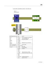
Страница 25: ...25 BA023001 en ...
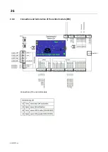
Страница 26: ...26 BA023001 en 2 4 4 Connection and termination of the central module ZM Connection of the central module ...
Страница 53: ...53 BA023001 en ...
Страница 138: ...138 BA023001 en 13 Annex 13 1 Naming convention ...


