50
BA023001-en
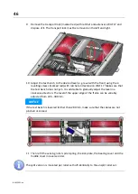
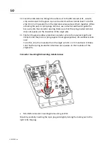
10 Feed the CAN data line through the cable duct to the ZM connector X1, untwist,
strip and connect to the green 4-pin connector X1 without tensile load. To do this,
strip 10 mm of insulation from the individual wires and twist them together. While
actuating the push-in spring-cage terminal, use a small screwdriver to guide the
bare wire into the connector opening. Make sure that the spring-loaded terminal
does not squeeze on the insulation of the single wire.
11 Shorten the green/yellow protective conductor wire to the required length and
clamp it onto the push-in spring-cage terminal (green/yellow) -X1L without tensile
load.
To do this, strip the insulation from the single wire 10...12 mm and twist it. Make
sure that the spring-loaded terminal does not squeeze on the insulation of the
single wire.
Connector mounting/dismounting: detailed views
•
M12 CAN connector mounting/dismounting on IFM
Mount by carefully inserting the 4-pin plug and slightly turning the locking nut to the
right to fix the plug.
Содержание CONNECT Series
Страница 19: ...19 BA023001 en 2 3 2 Set up diagram Set up diagram I ...
Страница 20: ...20 BA023001 en Set up diagram II ...
Страница 22: ...22 BA023001 en 2 4 1 Wiring diagram ...
Страница 23: ...23 BA023001 en 2 4 2 Control cabinet structure Basic variant ...
Страница 24: ...24 BA023001 en 2 4 3 Control cabinet structure Full equipment ...
Страница 25: ...25 BA023001 en ...
Страница 26: ...26 BA023001 en 2 4 4 Connection and termination of the central module ZM Connection of the central module ...
Страница 53: ...53 BA023001 en ...
Страница 138: ...138 BA023001 en 13 Annex 13 1 Naming convention ...


