10
BA023001-en
4
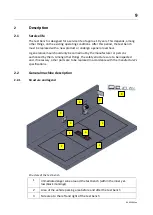
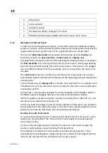
Brake tester
5
Control cabinet
6
Universal console
7
Simultaneous display, analogue / TV screen
8
Mobile devices (browser capable) with touch screen / WiFi router
2.2.2
Description of the test bench
In order to prevent dangerous situations in road traffic caused by a defective braking
system of a vehicle, motor vehicles should be subjected to a brake performance test at
regular intervals and e.g. after repairs. This is generally done on a brake tester.
The present
roller brake tester
allows wheel- and axle-wise dynamic
braking
and
essentially consists of a
base assembly
, a
control unit
and a
display unit
.
Components for driving the rollers and for absorbing the braking forces are installed in
the
floor assembly
: Test roller(s), sensing roller(s), drive motors, strain gauge bending
beam for measuring the braking force and various sensors. These sensors are plugged
into an interface module in the floor assembly, which is connected to the control unit
via cable.
The
control unit
consists of a control box with electronic components and a central
control board (central module) with firmware and the operating elements required for
safe operation.
In the simplest case, the
display unit
is a monitor of an existing PC or a notebook in the
immediate vicinity of the test bench and is connected to the control unit via LAN cable
or wirelessly via WiFi.
Furthermore, a commercially available TV monitor (together with a MAHA C_BOX) or
the MAHA universal analogue display can be used as a simultaneous display.
If WiFi is available, a browser-capable smart device (mobile phone, tablet PC, etc.) can
also be used as a display and operating unit.
On the one hand, the display is used for status indication of the system, user guidance
and visualization of the measured values; on the other hand, operating options can be
selected or data can be stored with the corresponding input device.
Function of a roller brake tester
To measure the braking forces of a motor vehicle, the test bench is driven over with a
vehicle axle. The wheel(s) of the motor vehicle is/are brought to a preset speed by
motor-driven rollers.
As soon as the set engine speed is reached, the operator is prompted to apply the
service or parking brake, slowly increasing the braking force.
The rotatably mounted drive motor would rotate freely during operation. This is
prevented by the bending beam (range spring). This connects the housing of the drive
motor to the test bench frame and thus forms a torque support.
Содержание CONNECT Series
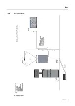
Страница 19: ...19 BA023001 en 2 3 2 Set up diagram Set up diagram I ...
Страница 20: ...20 BA023001 en Set up diagram II ...
Страница 22: ...22 BA023001 en 2 4 1 Wiring diagram ...
Страница 23: ...23 BA023001 en 2 4 2 Control cabinet structure Basic variant ...
Страница 24: ...24 BA023001 en 2 4 3 Control cabinet structure Full equipment ...
Страница 25: ...25 BA023001 en ...
Страница 26: ...26 BA023001 en 2 4 4 Connection and termination of the central module ZM Connection of the central module ...
Страница 53: ...53 BA023001 en ...
Страница 138: ...138 BA023001 en 13 Annex 13 1 Naming convention ...


