Reference Sheets for GRAFIK Eye Dimming Panel
36
Neon Tube Application
Information
Reference Sheet
Notes on Neon/Cold-Cathode Dimming
Overview
Successful dimming of neon and cold-cathode sources can be
achieved through proper equipment selection and installation. The
following installation suggestions and Luminous Tube Length Chart
for Dimming Applications must be used for optimum performance.
1. If equipment is selected and installed as specified here, a
dimming range of 95%-10% light should be possible.
2. The electrical properties of argon fill gas make it easier to dim
than red neon fill gas; therefore, installations using argon fill gas
will see a greater degree of success compared to neon
installations.
3. In addition to the following guidelines, all installations must
meet the NEC and local codes.
Lamps
1. Neon/cold-cathode lamps must be manufactured to proper lamp
pressurization (standard lamp pressure) without impurities. If
pressurization is not standard or impurities are present, poor
performance will result.
2. Neon/cold-cathode tubing should be well supported to avoid
rattling when dimmed.
3. Lutron recommends using only the transformer/tube
combinations spelled out in the Luminous Tube Length Chart for
Dimming Applications. Other combinations will result in poor
performance and flicker. Note that there are few successful
combinations for red neon tubes smaller than 11 mm.
4. Ends of tubes must be insulated to avoid arcing and subsequent
lamp instability.
Transformers
1. Normal power factor transformers must be used; electronic
transformers are not dimmable.
2. When choosing transformer secondary currents, it is important
to note that the higher the transformer current rating, the brighter
the light from the tube.
3. Transformers must be sized according to the chart. These
modified charts must be used by neon/cold-cathode transformer
suppliers to size the transformer for dimming applications. Stan-
dard luminous tube length charts must not be used to size
transformers in dimming applications as poor performance will
result.
4. Transformers must be thermally-protected or fused.
5. Power factor correction capacitors, if present must be
disconnected. If power correction is required, contact the toll-
free
Lutron Hotline
for details on power factor correction at the
lighting controller.
6. Transformers should be sized to run as close as possible to full
load footage as shown in the chart.
Wiring
1. Optimal dimming performance is achieved when the high voltage
(GTO-15) cable connecting a transformer output terminal to a
cold-cathode tube is enclosed in plastic conduit or run without
conduit. If code requires metal conduit, aluminum is preferred.
2. The total length of all GTO-15 cable connecting a transformer to
the cold-cathode tubes must be:
Twenty feet or Less if enclosed in plastic or no conduit; 6 ft. or
Less if enclosed in Metal Conduit
3. Braided or shielded GTO-15 cable must not be used for dimming
applications.
4. Lutron recommends that only one GTO-15 cable be run per
conduit.
5. All GTO-15 cables should be spaced a minimum of 4” from any
other GTO-15 cable.
6. Make sure spacing from tube ends to ground (earth) and other
tube ends is adequate to prevent arcing and subsequent lamp
instability.
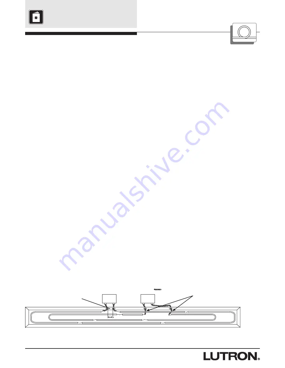
Note:
Make sure spacing between any tubing, tubing ends, high voltage secondary cable, or conduit to any grounded (earthed) surface is
adequate to prevent arcing and subsequent lamp instability.
1
2
> 4 in. (10 cm)
Any GTO-15 cable or conduit must be at least
4 in. (10 cm) from other GTO-15 cable or
conduit.
Total GTO-15 length per transformer must be < 20
ft. (9m) if in plastic or no conduit, or < 6 ft. (2m) if
in metal conduit.
GTO-15 Cable


