


32
g. Second IF
amplifier, adjustment of T-503 and T-504.— Replace V-501. Disconnect the
cable connected to J-202 on the RF chassis. Connect the scope to first limiter grid (pin 1 of V-
503). Solder a 10 Ohm resistor between pin 1 of V-501 and ground of the tube socket
mounting strap nut. Solder a 200 Ohm resistor to pin #1. Connect the sweep generator
between the 200 Ohm resistor and ground on the grounded lead of the 10 Ohm resistor. Set
the sweep generator output as required to produce a peak scope deflection of 0.25 Volts.
Adjust T-503 (primary) and T-504 (secondary) for a symmetrical response curve centered
around 21.4 Mc. The response shape should be flat-topped or slightly double-peaked.
After the adjustment is completed, remove the 10 and the 200 Ohm resistors.
h. First IF Amplifier, adjustment of T-501 and T-502.- Reconnect the cable to J-202. Install
the IF bottom cover and tighten all the mounting screws. Connect the scope to first limiter
grid (pin 1 of V-503). Connect the sweep generator to TP-202 (on the RF chassis) and ground
on one of the trimmer capacitor studs. Set the sweep generator output as required to produce
0.25 Volts peak scope deflection. Adjust T-501 (primary) and T-502 (secondary) for a
symmetrical response centered around 21.4 Mc.
The response shape should be very nearly flat-topped.
“Slave” 200 Kc. IF Channel Alignment
Turn on power. Set receiver tuning dial to lowest frequency and remove local oscillator tube
V-204 in the “Master” Tuner.
d. 3rd IF amplifier, adjustment of T-307 and T-308. - Remove second IF amplifier V-302
from its socket. Connect the scope to the cathode of the detector diode CR-301.
Connect the sweep generator between the third IF amplifier grid (pin 1 of V-303) and ground
on the tube socket mounting strap nut. Set the sweep generator output to maximum. Adjust
T-507 and T-508 (alternatively) for a symmetrical response centered around the center
frequency marker at 21.4 Mc.
e. 3rd-2nd IF amplifier, adjustment of T-305 and T-306. - Replace V-302 and remove V-301.
Connect the scope to the 3rd IF amplifier grid (pin 1 of V-303). Connect the sweep generator
between pin 1
of the second IF amplifier V-302 and ground on the tube socket mounting strap
Содержание G-187
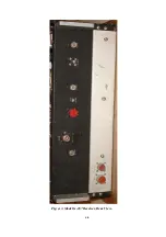
Страница 7: ...7 Figure 1 1 Model G 187 Special Purpose Receiver Front View...
Страница 9: ...9 Table 1 2 Semiconductor and Tube Complement...
Страница 10: ...10 Table 1 2 Semiconductor and Tube Complement continued...
Страница 14: ...14 Fig 2 1 Block Diagram Model G 187 Receiver...
Страница 44: ...44 Fig 4 1 Model G 187 Receiver Top View Cover Removed...
Страница 45: ...45 Fig 4 2 Model G 187 Receiver Bottom View Covers Removed...
Страница 46: ...46 Fig 4 3 Model G 187 Receiver Rear View...
Страница 47: ...47 Fig 4 4 Model G 187 Receiver Panoramic Top View Cover Removed...
Страница 48: ...48 Fig 4 5 Model G 187 Receiver Panoramic Top View Left Side Cover Removed...
Страница 49: ...49 Fig 4 6 Model G 187 Receiver Panoramic Top View Right Side Cover Removed...
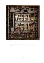
Страница 50: ...50 Fig 4 7 Model G 187 Receiver Panoramic Bottom View Covers Removed...
Страница 51: ...51 Fig 4 8 Model G 187 Receiver Panoramic Bottom View Left Side Covers Removed...
Страница 52: ...52 Fig 4 9 Model G 187 Receiver Panoramic Bottom View Right Side Covers Removed...
Страница 53: ...53 Table 4 2 Model G 187 Receiver Component Boards Lists...
Страница 54: ...54 Fig 4 10 Model G 187 Receiver Large Component Board...
Страница 56: ...56 Fig 4 14 Model G 187 Receiver Master Slave RF Tuners Top View...
Страница 57: ...57 Fig 4 15 Model G 187 Receiver Master Slave Tuners Bottom View Covers Removed...
Страница 58: ...58 Fig 4 16 Model G 187 Receiver Master Slave Tuners Panoramic Bottom View Covers Removed...
Страница 59: ...59 Fig 4 17 Model G 187 Receiver Master RF Tuner Bottom View Cover Removed...
Страница 60: ...60 Fig 4 18 Model G 187 Receiver Slave RF Tuner Bottom View Cover Removed...
Страница 67: ...67 Fig 5 1 Model G 187 Receiver Schematic Diagram Master RF Tuner...
Страница 68: ...68 Fig 5 2 Model G 187 Receiver Schematic Diagram Slave RF Tuner...
Страница 69: ...69 Fig 5 3 Model G 187 Receiver Schematic Diagram 21 4 Mc 200 Kc BW IF Strip Master and Slave Channels...
Страница 70: ...70 Fig 5 4 Model G 187 Receiver Schematic Diagram 2 5 Mc 40 Kc BW IF Nuvistor Strip Master and Slave Channels...
Страница 71: ...71 Fig 5 5 Model G 187 Receiver Schematic Diagram Main Chassis Circuits...
Страница 72: ...72 Fig 5 6 Model G 187 Receiver Schematic Diagram Mainframe...
Страница 73: ...73 Fig 5 7 Model G 187 Receiver Schematic Diagram Power Supply Circuits...
Страница 74: ...74 Fig 5 8 Model G 187 Receiver Schematic Diagram Various Details...