


21
In FM mode, V-610 (7587) acts as the first limiter and V-611 (7587) as the second limiter,
while two solid-state diodes (CR-602 and CR-603) form the discriminator circuit.
e. FUNCTION SWITCH IN 40 Kc AM POSITION, MASTER IF CHANNEL
Plate and screen voltage are removed from both the channels of the 21.4 Mc IF amplifier
subchassis and a 21.4 Mc signal is coupled from T-602 to the grid of V-606 (6CW4), that
together with V-607 (6CW4) forms a 2.5 Mc cascode mixer. V-608 (6CW4) is the 18.9 Mc
crystal controlled 2nd conversion oscillator, that is capacitively coupled to the above
mentioned cascode circuit.
The output of the 2.5 Mc mixer is coupled to V-609 (7587), a 2.5 Mc amplifier, and then is
fed to V-610 (7587) through L-606 and L-607, which, together, comprise a 2.5 Mc double-
tuned 40 Kc. Pass-Band filter.
In AM mode, V-610 (7587) acts as a further 2.5 Mc IF amplifier and V-611 (7587) as an AM
detector. A self-resonant choke is connected in the AM output lead to prevent IF signals from
leaving the IF subassembly.
f. FUNCTION SWITCH IN 40 Kc FM OR AM POSITION, SLAVE IF CHANNEL
Again, plate and screen voltage are removed from both the channels of the 21.4 Mc IF
amplifier subchassis and a 21.4 Mc signal is here coupled from T-601 to the grid of V-601
(6CW4), that together with V-602 (6CW4) forms a 2.5 Mc cascode mixer. V-603 (6CW4) is
the 18.9 Mc crystal controlled 2nd conversion oscillator, that is capacitively coupled to the
above mentioned cascode circuit.
The output of the 2.5 Mc mixer is coupled to V-604 (7587), a 2.5 Mc amplifier, and then is
fed to V-605 (7587) through L-602 and L-603, which, together, comprise a 2.5 Mc double-
tuned 40 Kc. Pass-Band filter.
V-605 (7587) acts as a further 2.5 Mc IF amplifier and a solid-state diode (CR-601) acts as a
detector.
Also the output of the “Slave” 40 Kc IF channel is used for various purposes (AGC, signal
strength meter M-101, direction finding) whose output is used for various purposes (AGC,
signal strength meter M-101, direction finding) .
Содержание G-187
Страница 7: ...7 Figure 1 1 Model G 187 Special Purpose Receiver Front View...
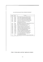
Страница 9: ...9 Table 1 2 Semiconductor and Tube Complement...
Страница 10: ...10 Table 1 2 Semiconductor and Tube Complement continued...
Страница 14: ...14 Fig 2 1 Block Diagram Model G 187 Receiver...
Страница 44: ...44 Fig 4 1 Model G 187 Receiver Top View Cover Removed...
Страница 45: ...45 Fig 4 2 Model G 187 Receiver Bottom View Covers Removed...
Страница 46: ...46 Fig 4 3 Model G 187 Receiver Rear View...
Страница 47: ...47 Fig 4 4 Model G 187 Receiver Panoramic Top View Cover Removed...
Страница 48: ...48 Fig 4 5 Model G 187 Receiver Panoramic Top View Left Side Cover Removed...
Страница 49: ...49 Fig 4 6 Model G 187 Receiver Panoramic Top View Right Side Cover Removed...
Страница 50: ...50 Fig 4 7 Model G 187 Receiver Panoramic Bottom View Covers Removed...
Страница 51: ...51 Fig 4 8 Model G 187 Receiver Panoramic Bottom View Left Side Covers Removed...
Страница 52: ...52 Fig 4 9 Model G 187 Receiver Panoramic Bottom View Right Side Covers Removed...
Страница 53: ...53 Table 4 2 Model G 187 Receiver Component Boards Lists...
Страница 54: ...54 Fig 4 10 Model G 187 Receiver Large Component Board...
Страница 56: ...56 Fig 4 14 Model G 187 Receiver Master Slave RF Tuners Top View...
Страница 57: ...57 Fig 4 15 Model G 187 Receiver Master Slave Tuners Bottom View Covers Removed...
Страница 58: ...58 Fig 4 16 Model G 187 Receiver Master Slave Tuners Panoramic Bottom View Covers Removed...
Страница 59: ...59 Fig 4 17 Model G 187 Receiver Master RF Tuner Bottom View Cover Removed...
Страница 60: ...60 Fig 4 18 Model G 187 Receiver Slave RF Tuner Bottom View Cover Removed...
Страница 67: ...67 Fig 5 1 Model G 187 Receiver Schematic Diagram Master RF Tuner...
Страница 68: ...68 Fig 5 2 Model G 187 Receiver Schematic Diagram Slave RF Tuner...
Страница 69: ...69 Fig 5 3 Model G 187 Receiver Schematic Diagram 21 4 Mc 200 Kc BW IF Strip Master and Slave Channels...
Страница 70: ...70 Fig 5 4 Model G 187 Receiver Schematic Diagram 2 5 Mc 40 Kc BW IF Nuvistor Strip Master and Slave Channels...
Страница 71: ...71 Fig 5 5 Model G 187 Receiver Schematic Diagram Main Chassis Circuits...
Страница 72: ...72 Fig 5 6 Model G 187 Receiver Schematic Diagram Mainframe...
Страница 73: ...73 Fig 5 7 Model G 187 Receiver Schematic Diagram Power Supply Circuits...
Страница 74: ...74 Fig 5 8 Model G 187 Receiver Schematic Diagram Various Details...