


11
SECTION 1
GENERAL DESCRIPTION
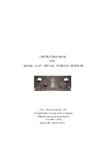
1. PURPOSE OF EQUIPMENT
The Model G-187 Special Purpose Receiver has been specifically designed to meet the
requirements of a highly stable, extremely sensitive AM-FM receiver for critical application
in the 55 to 260 Mc. range and for Direction Finding purposes specifically.
The receiver has a self-contained power supply and is capable of operation from a power
source of 115 Volts +/- 10%, 50 to 60 /- 5%
,
single phase, alternating current.
The particular features of the G-187 receiver include the following: a dual-tuner and dual-IF
channel system; a carrier operated relay (COR) which may be used to control auxiliary
equipment; an audio squelch with adjustable threshold; FM and AM reception with very low
distortion with selective IF bandwidths of 200 or 40 Kc; a separate high-quality 600 ohm
audio output; a video output and a special control signal output (for direction-finding
purposes).
For further details concerning the capabilities and special features of the Model G-187
receiver, see table 1-1, Performance Specifications.
2. DESCRIPTION OF EQUIPMENT
The Model G-187 receiver is 7 inches high by 19 inches wide by 19-7/8 inches deep and it
weighs approximately 40 pounds.
Panel and chassis are of aluminum construction, and the front panel has a black plexiglass
outer covering with aeronautical-style grazing light lamps mounted on it.
The panel is designed for standard 19 inch relay rack mounting, although the receiver is
equipped with dust covers and side panels, and may be used independently on a shelf or table.
The receiver uses single-conversion (with an IF value of 21.4 Mc) for the 200 Kc. bandwidth
(AM or FM modes) and double-conversion (IF values: 21.4 Mc. and 2.5 Mc.) for the 40 Kc.
bandwidth (AM of FM modes).
Содержание G-187
Страница 7: ...7 Figure 1 1 Model G 187 Special Purpose Receiver Front View...
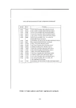
Страница 9: ...9 Table 1 2 Semiconductor and Tube Complement...
Страница 10: ...10 Table 1 2 Semiconductor and Tube Complement continued...
Страница 14: ...14 Fig 2 1 Block Diagram Model G 187 Receiver...
Страница 44: ...44 Fig 4 1 Model G 187 Receiver Top View Cover Removed...
Страница 45: ...45 Fig 4 2 Model G 187 Receiver Bottom View Covers Removed...
Страница 46: ...46 Fig 4 3 Model G 187 Receiver Rear View...
Страница 47: ...47 Fig 4 4 Model G 187 Receiver Panoramic Top View Cover Removed...
Страница 48: ...48 Fig 4 5 Model G 187 Receiver Panoramic Top View Left Side Cover Removed...
Страница 49: ...49 Fig 4 6 Model G 187 Receiver Panoramic Top View Right Side Cover Removed...
Страница 50: ...50 Fig 4 7 Model G 187 Receiver Panoramic Bottom View Covers Removed...
Страница 51: ...51 Fig 4 8 Model G 187 Receiver Panoramic Bottom View Left Side Covers Removed...
Страница 52: ...52 Fig 4 9 Model G 187 Receiver Panoramic Bottom View Right Side Covers Removed...
Страница 53: ...53 Table 4 2 Model G 187 Receiver Component Boards Lists...
Страница 54: ...54 Fig 4 10 Model G 187 Receiver Large Component Board...
Страница 56: ...56 Fig 4 14 Model G 187 Receiver Master Slave RF Tuners Top View...
Страница 57: ...57 Fig 4 15 Model G 187 Receiver Master Slave Tuners Bottom View Covers Removed...
Страница 58: ...58 Fig 4 16 Model G 187 Receiver Master Slave Tuners Panoramic Bottom View Covers Removed...
Страница 59: ...59 Fig 4 17 Model G 187 Receiver Master RF Tuner Bottom View Cover Removed...
Страница 60: ...60 Fig 4 18 Model G 187 Receiver Slave RF Tuner Bottom View Cover Removed...
Страница 67: ...67 Fig 5 1 Model G 187 Receiver Schematic Diagram Master RF Tuner...
Страница 68: ...68 Fig 5 2 Model G 187 Receiver Schematic Diagram Slave RF Tuner...
Страница 69: ...69 Fig 5 3 Model G 187 Receiver Schematic Diagram 21 4 Mc 200 Kc BW IF Strip Master and Slave Channels...
Страница 70: ...70 Fig 5 4 Model G 187 Receiver Schematic Diagram 2 5 Mc 40 Kc BW IF Nuvistor Strip Master and Slave Channels...
Страница 71: ...71 Fig 5 5 Model G 187 Receiver Schematic Diagram Main Chassis Circuits...
Страница 72: ...72 Fig 5 6 Model G 187 Receiver Schematic Diagram Mainframe...
Страница 73: ...73 Fig 5 7 Model G 187 Receiver Schematic Diagram Power Supply Circuits...
Страница 74: ...74 Fig 5 8 Model G 187 Receiver Schematic Diagram Various Details...