


15
SECTION 2
THEORY OF OPERATION
1. ANALYSIS, MODEL G-187 RECEIVER
a. A block diagram of the Model G-187 receiver is shown in Figure 2-1.
The circuit, with the function switch in the 200 Kc AM or FM position is a single
superheterodyne with an IF of 21.4 Mc. With the function switch in the 40 Kc AM or FM
position, a dual-conversion circuit is used, with a 21.4 Mc first IF, followed by a 2.5 Mc
second IF.
Each of the separate IF channels used for the available bandwidths has been built in a two-
section arrangement: one section is fed from the “Master Tuner” output and the other from the
“Slave Tuner” output. The “Master” section is used for FM and AM signal demodulation,
while the “Slave” section produces special outputs for AGC and Direction Finding purposes
and is not directly involved with signal intelligence.
The 2.5 Mc IF strips and double-conversion are used for the 40 Kc bandwidth only and make
use of a special kind of tubes (called “Nuvistor”) in a separate subchassis that is fastened to
the left side of the receiver. Such a subchassis is the “FM-75J-100 IF strip” that was built by
CEI.
The two RF tuners are designed to produce the lowest possible noise figure consistent with
the type tube used (a 416B first RF amplifier} and a practical tuning structure capable of
tuning 55 to 260 mc, with reasonably uniform performance over the band.
The basic tuning element in both the tuners is a Mallory type S-4 spiral inductuner. The input
circuit is broadly tuned by the first section of the inductuner. The second and third sections
double tune a bandpass filter to produce a high gain with a minimum response to spurious
signals. Adjustable coupling is provided by a capacitive "tee" section between the input and
output sections of the bandpass filter. The remaining inductuner section is used as the
oscillator tank inductance in the “Master” tuner and as a simple tuning device in the plate
circuit of the oscillator buffer in the “Slave” tuner.
Содержание G-187
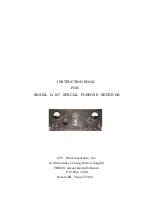
Страница 7: ...7 Figure 1 1 Model G 187 Special Purpose Receiver Front View...
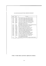
Страница 9: ...9 Table 1 2 Semiconductor and Tube Complement...
Страница 10: ...10 Table 1 2 Semiconductor and Tube Complement continued...
Страница 14: ...14 Fig 2 1 Block Diagram Model G 187 Receiver...
Страница 44: ...44 Fig 4 1 Model G 187 Receiver Top View Cover Removed...
Страница 45: ...45 Fig 4 2 Model G 187 Receiver Bottom View Covers Removed...
Страница 46: ...46 Fig 4 3 Model G 187 Receiver Rear View...
Страница 47: ...47 Fig 4 4 Model G 187 Receiver Panoramic Top View Cover Removed...
Страница 48: ...48 Fig 4 5 Model G 187 Receiver Panoramic Top View Left Side Cover Removed...
Страница 49: ...49 Fig 4 6 Model G 187 Receiver Panoramic Top View Right Side Cover Removed...
Страница 50: ...50 Fig 4 7 Model G 187 Receiver Panoramic Bottom View Covers Removed...
Страница 51: ...51 Fig 4 8 Model G 187 Receiver Panoramic Bottom View Left Side Covers Removed...
Страница 52: ...52 Fig 4 9 Model G 187 Receiver Panoramic Bottom View Right Side Covers Removed...
Страница 53: ...53 Table 4 2 Model G 187 Receiver Component Boards Lists...
Страница 54: ...54 Fig 4 10 Model G 187 Receiver Large Component Board...
Страница 56: ...56 Fig 4 14 Model G 187 Receiver Master Slave RF Tuners Top View...
Страница 57: ...57 Fig 4 15 Model G 187 Receiver Master Slave Tuners Bottom View Covers Removed...
Страница 58: ...58 Fig 4 16 Model G 187 Receiver Master Slave Tuners Panoramic Bottom View Covers Removed...
Страница 59: ...59 Fig 4 17 Model G 187 Receiver Master RF Tuner Bottom View Cover Removed...
Страница 60: ...60 Fig 4 18 Model G 187 Receiver Slave RF Tuner Bottom View Cover Removed...
Страница 67: ...67 Fig 5 1 Model G 187 Receiver Schematic Diagram Master RF Tuner...
Страница 68: ...68 Fig 5 2 Model G 187 Receiver Schematic Diagram Slave RF Tuner...
Страница 69: ...69 Fig 5 3 Model G 187 Receiver Schematic Diagram 21 4 Mc 200 Kc BW IF Strip Master and Slave Channels...
Страница 70: ...70 Fig 5 4 Model G 187 Receiver Schematic Diagram 2 5 Mc 40 Kc BW IF Nuvistor Strip Master and Slave Channels...
Страница 71: ...71 Fig 5 5 Model G 187 Receiver Schematic Diagram Main Chassis Circuits...
Страница 72: ...72 Fig 5 6 Model G 187 Receiver Schematic Diagram Mainframe...
Страница 73: ...73 Fig 5 7 Model G 187 Receiver Schematic Diagram Power Supply Circuits...
Страница 74: ...74 Fig 5 8 Model G 187 Receiver Schematic Diagram Various Details...