


12
The two bandwidth values are obtained through separate IF channels (the 21.4 Mc. - 200 KHz
one using conventional miniature vacuum tubes, the 2.5 Mc. - 40 Kc. one using nuvistors
instead), by properly switching the H.V. supply to the involved subchassis.
Both the IF amplifiers are "doubled units" (one section is fed by the "Master" RF Tuner and
the other one by the "Slave" RF Tuner, so there are four IF channels total in the receiver).
For each mode and bandwidth, the "Master" RF-IF channel provides to the signal treatment
and intelligence, while the "Slave" RF-IF Channel produces special outputs (suitable for
direction finding purposes) and is also used for driving the signal strength meter and for AGC.
The two RF Tuners are identical each other but as for the oscillator circuit (a common
oscillator stage is employed for both the mixers and it is allocated in the "Master Tuner");
both of them make use of a 4-Section Mallory "Inductuner" each.
The RF Tuners employed in the G-187 receiver derive directly from the ones that Nems-
Clarke Co. used in their "1302" and "1502" receivers.
Inductuners are mechanically tuned variable inductors for VHF and UHF applications that are
tuned using a common rotary shaft moving contacts along single turn or spiral silver coils.
This is a product Mallory has been making since the 1940s and it is still used in military
communications equipment and precision test instruments.
The advantage of the Inductuner over other variable inductance devices is its stability and
repeatability; it operates on the principle that inductance of two lines, shorted at one end, is
proportional to the area that these lines enclose. Two such lines are laid concentrically on a
coil form and a shorting contactor, connected to the tuning shaft, is allowed to be moved
along their length, changing the inductance.
The tuning dial on the G-187 receiver series is a spiral scale printed on 1/8" thick translucent
plastic disk illuminated from behind. A small crescent-shaped window mask, sliding
vertically, tracks each spiral showing on the relevant part as the radio is tuned. This dial
mechanism is a common item in some Nems-Clarke and CEI equipments. All the receiver
circuits are built as completely shielded subassemblies with most of the audio and video
Содержание G-187
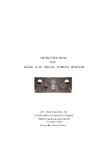
Страница 7: ...7 Figure 1 1 Model G 187 Special Purpose Receiver Front View...
Страница 9: ...9 Table 1 2 Semiconductor and Tube Complement...
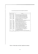
Страница 10: ...10 Table 1 2 Semiconductor and Tube Complement continued...
Страница 14: ...14 Fig 2 1 Block Diagram Model G 187 Receiver...
Страница 44: ...44 Fig 4 1 Model G 187 Receiver Top View Cover Removed...
Страница 45: ...45 Fig 4 2 Model G 187 Receiver Bottom View Covers Removed...
Страница 46: ...46 Fig 4 3 Model G 187 Receiver Rear View...
Страница 47: ...47 Fig 4 4 Model G 187 Receiver Panoramic Top View Cover Removed...
Страница 48: ...48 Fig 4 5 Model G 187 Receiver Panoramic Top View Left Side Cover Removed...
Страница 49: ...49 Fig 4 6 Model G 187 Receiver Panoramic Top View Right Side Cover Removed...
Страница 50: ...50 Fig 4 7 Model G 187 Receiver Panoramic Bottom View Covers Removed...
Страница 51: ...51 Fig 4 8 Model G 187 Receiver Panoramic Bottom View Left Side Covers Removed...
Страница 52: ...52 Fig 4 9 Model G 187 Receiver Panoramic Bottom View Right Side Covers Removed...
Страница 53: ...53 Table 4 2 Model G 187 Receiver Component Boards Lists...
Страница 54: ...54 Fig 4 10 Model G 187 Receiver Large Component Board...
Страница 56: ...56 Fig 4 14 Model G 187 Receiver Master Slave RF Tuners Top View...
Страница 57: ...57 Fig 4 15 Model G 187 Receiver Master Slave Tuners Bottom View Covers Removed...
Страница 58: ...58 Fig 4 16 Model G 187 Receiver Master Slave Tuners Panoramic Bottom View Covers Removed...
Страница 59: ...59 Fig 4 17 Model G 187 Receiver Master RF Tuner Bottom View Cover Removed...
Страница 60: ...60 Fig 4 18 Model G 187 Receiver Slave RF Tuner Bottom View Cover Removed...
Страница 67: ...67 Fig 5 1 Model G 187 Receiver Schematic Diagram Master RF Tuner...
Страница 68: ...68 Fig 5 2 Model G 187 Receiver Schematic Diagram Slave RF Tuner...
Страница 69: ...69 Fig 5 3 Model G 187 Receiver Schematic Diagram 21 4 Mc 200 Kc BW IF Strip Master and Slave Channels...
Страница 70: ...70 Fig 5 4 Model G 187 Receiver Schematic Diagram 2 5 Mc 40 Kc BW IF Nuvistor Strip Master and Slave Channels...
Страница 71: ...71 Fig 5 5 Model G 187 Receiver Schematic Diagram Main Chassis Circuits...
Страница 72: ...72 Fig 5 6 Model G 187 Receiver Schematic Diagram Mainframe...
Страница 73: ...73 Fig 5 7 Model G 187 Receiver Schematic Diagram Power Supply Circuits...
Страница 74: ...74 Fig 5 8 Model G 187 Receiver Schematic Diagram Various Details...