16
The IF amplifiers, with the function switch in the 200 Kc. FM position, use two stages of
amplification, cascade limiters and a phase-shift discriminator. With the function switch in the
200 Kc. AM position, AGC voltage is applied to the first two stages, and the second limiter
becomes the AM detector. With the function switch in the 40 Kc. FM or AM position, plate
voltage is removed from the 21.4 Mc IF amplifiers and applied to the 2.5 Mc dual conversion
mixer and IF amplifier channels.
The output signal of the two “Master” IF strips (200 Kc. AM and FM or 40 Kc. AM and FM)
drives a two-stage direct-coupled video amplifier with cathode follower output. A portion of
the follower output drives a four-stage squelch-audio amplifier circuit whose output is fed to
the J-108 connector (a 19-pole round female connector of the Deutsch “DS” Series) placed in
the rear apron of the receiver.
During either AM or FM operation the carrier operated relay (COR) is actuated by AGC
voltage from the stage which functions as either a detector or second limiter. The COR
controls a light and two sets of DT contacts (in the above mentioned J-108 connector) to
which auxiliary equipment can be connected.
To the same connector is also fed the output signal of the two “Slave” IF strips (200 Kc. AM
and FM or 40 Kc. AM and FM); it can be used for direction-finding purposes and is also
employed for the AGC circuits and for driving the signal strength meter.
2. "MASTER" AND "SLAVE" RF TUNERS
a. ANTENNA INPUTS
The main and auxiliary antenna inputs are two N-type connectors mounted on the chassis rear
apron, from which the signal is applied to each RF Tuner (“Master” and “Slave”).
The input impedance of each tuner is approximately 50 ohms over the frequency
range of 55 to 260 Mc.
b. FIRST RF STAGE (“MASTER” OR “SLAVE” TUNER)
The input signal is applied to the cathode of the 416B low noise planar triode.
Содержание G-187
Страница 7: ...7 Figure 1 1 Model G 187 Special Purpose Receiver Front View...
Страница 9: ...9 Table 1 2 Semiconductor and Tube Complement...
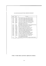
Страница 10: ...10 Table 1 2 Semiconductor and Tube Complement continued...
Страница 14: ...14 Fig 2 1 Block Diagram Model G 187 Receiver...
Страница 44: ...44 Fig 4 1 Model G 187 Receiver Top View Cover Removed...
Страница 45: ...45 Fig 4 2 Model G 187 Receiver Bottom View Covers Removed...
Страница 46: ...46 Fig 4 3 Model G 187 Receiver Rear View...
Страница 47: ...47 Fig 4 4 Model G 187 Receiver Panoramic Top View Cover Removed...
Страница 48: ...48 Fig 4 5 Model G 187 Receiver Panoramic Top View Left Side Cover Removed...
Страница 49: ...49 Fig 4 6 Model G 187 Receiver Panoramic Top View Right Side Cover Removed...
Страница 50: ...50 Fig 4 7 Model G 187 Receiver Panoramic Bottom View Covers Removed...
Страница 51: ...51 Fig 4 8 Model G 187 Receiver Panoramic Bottom View Left Side Covers Removed...
Страница 52: ...52 Fig 4 9 Model G 187 Receiver Panoramic Bottom View Right Side Covers Removed...
Страница 53: ...53 Table 4 2 Model G 187 Receiver Component Boards Lists...
Страница 54: ...54 Fig 4 10 Model G 187 Receiver Large Component Board...
Страница 56: ...56 Fig 4 14 Model G 187 Receiver Master Slave RF Tuners Top View...
Страница 57: ...57 Fig 4 15 Model G 187 Receiver Master Slave Tuners Bottom View Covers Removed...
Страница 58: ...58 Fig 4 16 Model G 187 Receiver Master Slave Tuners Panoramic Bottom View Covers Removed...
Страница 59: ...59 Fig 4 17 Model G 187 Receiver Master RF Tuner Bottom View Cover Removed...
Страница 60: ...60 Fig 4 18 Model G 187 Receiver Slave RF Tuner Bottom View Cover Removed...
Страница 67: ...67 Fig 5 1 Model G 187 Receiver Schematic Diagram Master RF Tuner...
Страница 68: ...68 Fig 5 2 Model G 187 Receiver Schematic Diagram Slave RF Tuner...
Страница 69: ...69 Fig 5 3 Model G 187 Receiver Schematic Diagram 21 4 Mc 200 Kc BW IF Strip Master and Slave Channels...
Страница 70: ...70 Fig 5 4 Model G 187 Receiver Schematic Diagram 2 5 Mc 40 Kc BW IF Nuvistor Strip Master and Slave Channels...
Страница 71: ...71 Fig 5 5 Model G 187 Receiver Schematic Diagram Main Chassis Circuits...
Страница 72: ...72 Fig 5 6 Model G 187 Receiver Schematic Diagram Mainframe...
Страница 73: ...73 Fig 5 7 Model G 187 Receiver Schematic Diagram Power Supply Circuits...
Страница 74: ...74 Fig 5 8 Model G 187 Receiver Schematic Diagram Various Details...


