


18
A blower motor mounted on the front end assembly is used to cool the 416B tube. The motor
plugs into the main chassis with a Jones plug. A jumper between two of the pins of the Jones
plug removes plate voltage from the 416B when the motor is disconnected, thus protecting the
tube.
Positive grid bias of 8 Volts is applied from a voltage divider from the 150 Volt regulated B+.
This voltage is necessary to cancel the cathode self-bias voitage of 8.2 Volts so that the tube
will operate with approximately 0.2 Volts bias. The D-C degeneration due to the large
cathode resistor has a considerable stabilizing effect on the 416B tube and minimizes
performance variations from one tube to the next if replacement becomes necessary.
If, for any reason, the grid bias voltage is shorted or removed, the plate current is reduced and
the tube will not be damaged.
d. MIXER (“MASTER” OR “SLAVE” TUNER)
A 6AK5 pentode is used as a converter. The oscillator signal is injected into the grid circuit,
developing an operating bias proportional to the amplitude of the local oscillator signal. This
causes a minimum effect on the receiver operation due to variations in local oscillator
amplitude. A de-coupled test point (TP-202) from a
tap on the mixer grid resistors provides a
convenient means for observing the response of the RF circuits.
The output signals from the mixers (IF signals) have a frequency of 21.4 Mc.
e. LOCAL OSCILLATOR (“MASTER” TUNER ONLY)
The local oscillator utilizes a 6AF4A tube in a modified Colpitts configuration. The end
inductors are made of heavy straps to insure frequency stability. The frequency stability of the
oscillator is very high due to the use of a high Gm tube which is loosely coupled to the high
Q tank circuit.
The Local Oscillator is present in the “Master” Tuner only and its signal is fed to the mixer
stages of both the tuners (directly in the “Master” Tuner and through a buffer stage in the
“Slave” Tuner). The oscillator signal is also fed (via the J-204 socket) to J-103, a BNC socket
in the rear apron of the receiver, so that the oscillator frequency can be precisely measured or
the signal used for other purposes.
Содержание G-187
Страница 7: ...7 Figure 1 1 Model G 187 Special Purpose Receiver Front View...
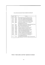
Страница 9: ...9 Table 1 2 Semiconductor and Tube Complement...
Страница 10: ...10 Table 1 2 Semiconductor and Tube Complement continued...
Страница 14: ...14 Fig 2 1 Block Diagram Model G 187 Receiver...
Страница 44: ...44 Fig 4 1 Model G 187 Receiver Top View Cover Removed...
Страница 45: ...45 Fig 4 2 Model G 187 Receiver Bottom View Covers Removed...
Страница 46: ...46 Fig 4 3 Model G 187 Receiver Rear View...
Страница 47: ...47 Fig 4 4 Model G 187 Receiver Panoramic Top View Cover Removed...
Страница 48: ...48 Fig 4 5 Model G 187 Receiver Panoramic Top View Left Side Cover Removed...
Страница 49: ...49 Fig 4 6 Model G 187 Receiver Panoramic Top View Right Side Cover Removed...
Страница 50: ...50 Fig 4 7 Model G 187 Receiver Panoramic Bottom View Covers Removed...
Страница 51: ...51 Fig 4 8 Model G 187 Receiver Panoramic Bottom View Left Side Covers Removed...
Страница 52: ...52 Fig 4 9 Model G 187 Receiver Panoramic Bottom View Right Side Covers Removed...
Страница 53: ...53 Table 4 2 Model G 187 Receiver Component Boards Lists...
Страница 54: ...54 Fig 4 10 Model G 187 Receiver Large Component Board...
Страница 56: ...56 Fig 4 14 Model G 187 Receiver Master Slave RF Tuners Top View...
Страница 57: ...57 Fig 4 15 Model G 187 Receiver Master Slave Tuners Bottom View Covers Removed...
Страница 58: ...58 Fig 4 16 Model G 187 Receiver Master Slave Tuners Panoramic Bottom View Covers Removed...
Страница 59: ...59 Fig 4 17 Model G 187 Receiver Master RF Tuner Bottom View Cover Removed...
Страница 60: ...60 Fig 4 18 Model G 187 Receiver Slave RF Tuner Bottom View Cover Removed...
Страница 67: ...67 Fig 5 1 Model G 187 Receiver Schematic Diagram Master RF Tuner...
Страница 68: ...68 Fig 5 2 Model G 187 Receiver Schematic Diagram Slave RF Tuner...
Страница 69: ...69 Fig 5 3 Model G 187 Receiver Schematic Diagram 21 4 Mc 200 Kc BW IF Strip Master and Slave Channels...
Страница 70: ...70 Fig 5 4 Model G 187 Receiver Schematic Diagram 2 5 Mc 40 Kc BW IF Nuvistor Strip Master and Slave Channels...
Страница 71: ...71 Fig 5 5 Model G 187 Receiver Schematic Diagram Main Chassis Circuits...
Страница 72: ...72 Fig 5 6 Model G 187 Receiver Schematic Diagram Mainframe...
Страница 73: ...73 Fig 5 7 Model G 187 Receiver Schematic Diagram Power Supply Circuits...
Страница 74: ...74 Fig 5 8 Model G 187 Receiver Schematic Diagram Various Details...