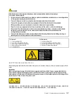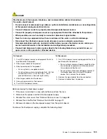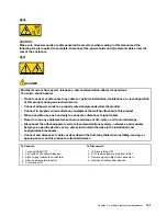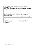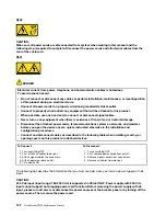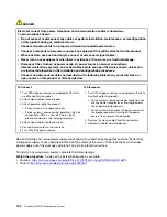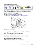
To Connect:
To Disconnect:
1. Turn OFF all power sources and equipment that is to
be attached to this product.
2. Attach signal cables to the product.
3. Attach power cords to the product.
• For ac systems, use appliance inlets.
• For dc systems, ensure correct polarity of -48 V dc
connections: RTN is + and -48 V dc is -. Earth
ground should use a two-hole lug for safety.
4. Attach signal cables to other devices.
5. Connect power cords to their sources.
6. Turn ON all the power sources.
1. Turn OFF all power sources and equipment that is to
be attached to this product.
• For ac systems, remove all power cords from the
chassis power receptacles or interrupt power at
the ac power distribution unit.
• For dc systems, disconnect dc power sources at
the breaker panel or by turning off the power
source. Then, remove the dc cables.
2. Remove the signal cables from the connectors.
3. Remove all cables from the devices.
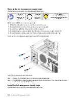
To remove a hot-swap power supply, complete the following steps:
Watch the procedure
. A video of the removal process is available:
• Youtube:
https://www.youtube.com/playlist?list=PLYV5R7hVcs-Acsjj4tU79GzKnWG316BYn
• Youku:
http://list.youku.com/albumlist/show/id_50483452
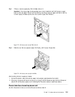
Step 1. If the server is in a rack, pull back the cable management arm to gain access to the rear of the
server and the power supply.
Step 2. Locate the failing power supply in the rear of your server.
Note:
On each power supply, there are three status LEDs near the power cord connector. For
information about the status LEDs, see “Rear view LEDs” on page 21.
Step 3. Disconnect the power cord from the failing hot-swap redundant power supply.
Note:
If you are replacing two power supplies, do the power supply replacement one by one to
ensure that the power supply to the server is not interrupted. Do not disconnect the power cord
from the secondly replaced power supply until the power output LED for the firstly replaced power
supply is lit.
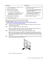
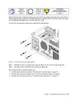
Step 4. Press the release tab toward the handle and carefully pull the handle at the same time to slide the
failing hot-swap power supply out of the chassis.
Figure 110. Hot-swap power supply removal
.
Hardware replacement procedures
149
Содержание ThinkSystem ST550 7X09
Страница 1: ...ThinkSystem ST550 Maintenance Manual Machine Types 7X09 and 7X10 ...
Страница 8: ...vi ThinkSystem ST550 Maintenance Manual ...
Страница 36: ...28 ThinkSystem ST550 Maintenance Manual ...
Страница 188: ...180 ThinkSystem ST550 Maintenance Manual ...
Страница 206: ...198 ThinkSystem ST550 Maintenance Manual ...
Страница 210: ...202 ThinkSystem ST550 Maintenance Manual ...
Страница 219: ......
Страница 220: ......


