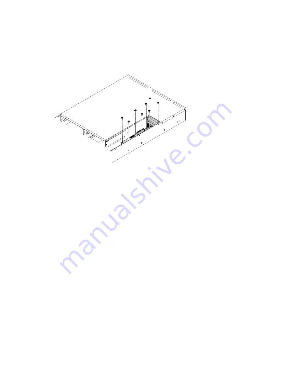
Step 5.
Remove the 6 6#32 screws from the system management board.
Step 6.
Remove the 2 M3 screws from the system management board bracket.
Step 7.
Place your fingers under the front and back of the top of the system management board and
backplane assembly; then, lift the system management board and backplane assembly out of
the server.
000
000
00
00
Figure 89. System management board and backplane assembly removal
Installing the system management board and backplane assembly
Use this information to replace the system management board and backplane assembly.
Read the safety information in “Safety” on page v and “Installation guidelines” on page 75.
If you are replacing a server component in the server, you need to slide the server out from the rack
enclosure, turn off the server and peripheral devices, and disconnect the power cords and all external cables.
To replace the system management board and backplane assembly, complete the following steps.
Step 1.
Align the system management board and backplane assembly pins with the pin holes on the server
chassis; then, lower the system management board and backplane assembly into the server. Press
the system management board and backplane assembly down until it is securely seated.
Removing and replacing server components
143
Содержание ThinkServer n400
Страница 5: ...Taiwan BSMI RoHS declaration 182 Index 183 Copyright Lenovo iii ...
Страница 184: ...168 Lenovo ThinkServer sd350 Server Type 5493 Lenovo ThinkServer n400 Enclosure Type 5495Installation and Service Guide ...
Страница 186: ...170 Lenovo ThinkServer sd350 Server Type 5493 Lenovo ThinkServer n400 Enclosure Type 5495Installation and Service Guide ...
Страница 190: ...174 Lenovo ThinkServer sd350 Server Type 5493 Lenovo ThinkServer n400 Enclosure Type 5495Installation and Service Guide ...
Страница 205: ......
Страница 206: ...Part Number 00MV565 Printed in China 1P P N 00MV565 1P00MV565 ...


