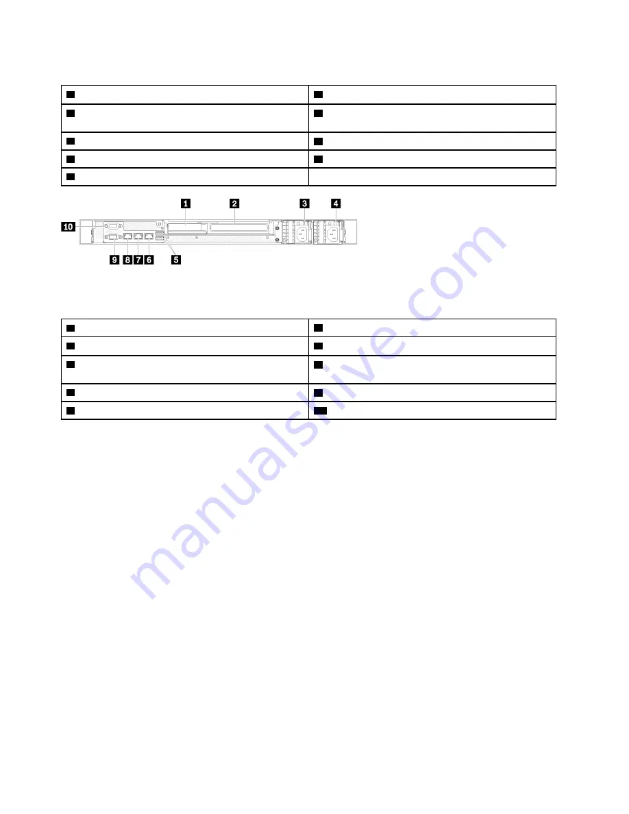
Table 4. Rear view - Non-redundant power supply model
1
PCIe slot 1
6
Ethernet connector 1 (shared with XCC network port)
2
PCIe slot 2
7
Dedicated Lenovo XClarity Controller (XCC) network
connector
3
Power connector
8
VGA connector
4
USB 3.2 Gen 2 connectors
9
Serial connector
5
Ethernet connector 2
Figure 13. Rear view - Redundant power supply model
Table 5. Rear view - Redundant power supply model
1
PCIe slot 1
6
Ethernet connector 2
2
PCIe slot 2
7
Ethernet connector 1 (shared with XCC network port)
3
Power connector 1
8
Dedicated Lenovo XClarity Controller (XCC) network
connector
4
Power connector 2
9
VGA connector
5
USB 3.2 Gen 2 connectors
10
Serial connector
PCIe slot 1 and 2
: Your server has PCIe slots on the system board for you to install appropriate PCIe
adapters. For information about the PCIe slots, see
“PCIe riser assembly” on page 24
Power connector 1 and 2
: Connect the power cord to this component.
USB 3.2 Gen 2 connectors
: Used to attach a device that requires a USB 3.2 connection, such as a
keyboard, a mouse, or a USB flash drive.
Ethernet connector 1 and 2
: Used to attach an Ethernet cable for a LAN. Each Ethernet connector has two
status LEDs to help you identify the Ethernet connectivity and activity. If the LOM adapter is not installed,
Ethernet connector 1 can be set as Lenovo XClarity Controller Network connector. To set Ethernet connector
1 as Lenovo XClarity Controller Network connector, start Setup Utility and select
BMC Settings
➙
Network
Settings
➙
Network Settings Network Interface Port : Shared
. Then, click
Shared NIC on
and select
Onboard Port 1
.
Dedicated Lenovo XClarity Controller (XCC) network connector
: Used to attach an Ethernet cable to
manage the system using Lenovo XClarity Controller.
VGA connector
: Used to attach a VGA-compatible video device, such as a VGA monitor.
Serial connector
: Connect a 9-pin serial device to this connector. The serial port is shared with the XCC.
The XCC can take control of the shared serial port to redirect serial traffic, using Serial over LAN (SOL).
18
ThinkSystem SR250 V2 Maintenance Manual
Содержание 7D7Q
Страница 1: ...ThinkSystem SR250 V2 Maintenance Manual Machine Types 7D7Q and 7D7R ...
Страница 8: ...vi ThinkSystem SR250 V2 Maintenance Manual ...
Страница 20: ...12 ThinkSystem SR250 V2 Maintenance Manual ...
Страница 35: ...2 5 inch drive model Figure 26 Server components 2 5 inch drive model Chapter 2 Server components 27 ...
Страница 42: ...34 ThinkSystem SR250 V2 Maintenance Manual ...
Страница 176: ...168 ThinkSystem SR250 V2 Maintenance Manual ...
Страница 180: ...172 ThinkSystem SR250 V2 Maintenance Manual ...
Страница 183: ......
Страница 184: ......


