background image

Group 7 

Data/Programming 

Page 143 

Release R1.03e 


LEIBINGER JET3 


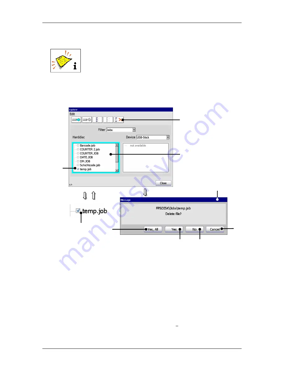
7.5.7.4 Delete jobs 


A job can only be deleted in the explorer!  


(Example: The job „temp“ should be deleted in the internal memory.) 


Figure 81 


Explorer (Delete job) 


1 – Selection window <Harddisc> 

5 – Button <Cancel> 


2 – Marked job 

6 – Button <No> 


3 – Tool <delete> 

7 – Button <Yes> 


4 – Message <Delete file> 

8 – Button <Yes, All> 


Proceeding: 


„


Click on the display area of the selection window 

<Harddisc>

 (1) to activate it. 

The border of the window is now displayed turquoise.  

„


Select the job with the designation“temp.job“ (2) by clicking on the control box 
or the designation. The selection is displayed with a 

 in the control box. 


Содержание JET3

Страница 1: ...ective equipment 17 2 8 Protective devices 17 2 9 Safety measures at the place of installation 18 2 10 Dangers through consumables 18 3 Accident prevention 20 3 1 Storage and handling normal use 20 3 2 First aid measures 21 3 3 Fire fighting measures 21 3 4 Measures in the event of accidental release spillage 22 4 Technical data 23 4 1 Dimensions weights connections 23 4 2 Electrical connection va...

Страница 2: ...Interface X2 Serial interface 40 5 4 7 USB Connection 40 6 Operation 41 6 1 Construction Structure of the device 41 6 2 Functional principle 42 6 2 1 Method of working 42 6 2 2 Drop creation 42 6 2 3 Drop charging 43 6 2 4 Drop deflection 43 6 2 5 Creation of a character 43 6 2 6 Summary of the individual procedures 44 6 2 7 Example of use 45 6 3 Essential operating and information elements 46 6 3...

Страница 3: ...2 7 3 Settings 73 7 3 1 Basic settings 74 7 3 1 1 Language and units 75 7 3 1 2 Date and time 77 7 3 1 3 Interval operation Set interval time 79 7 3 1 4 Encoder interface 81 7 3 1 5 Factory Settings 82 7 3 2 Password settings and user authorizations 84 7 3 2 1 Menu password settings 84 7 3 2 1 1 Selection of user level 86 7 3 2 1 2 Definition of password 86 7 3 2 1 3 Definition of user rights 87 7...

Страница 4: ... Product counter 113 7 5 3 1 Product counter settings 114 7 5 3 2 Stop after x products Pre defined print stop 116 7 5 3 3 Reset all job counters 118 7 5 4 Login 119 7 5 4 1 Layout and call login logout dialog 119 7 5 4 2 Login user or carry out user change 121 7 5 4 3 Logout user 122 7 5 5 Graphic editor 123 7 5 5 1 Edit tools 124 7 5 5 2 Organization tools 125 7 5 5 3 Drawing tools 126 7 5 5 4 D...

Страница 5: ...ools 157 8 3 Job editor management 158 8 3 1 Save job Save job as 158 8 3 2 Load job to print 160 8 3 3 Close job editor 162 8 4 Object settings 163 8 4 1 Font selection 164 8 4 2 Contrast value 165 8 4 3 Position settings 166 8 4 4 Bold level Bold text 166 8 4 5 ICG value 167 8 4 6 Orientation 167 8 4 7 Display settings 168 8 5 Parameter settings 169 8 5 1 Print parameter 169 8 5 1 1 PrintGo dela...

Страница 6: ...editor 185 8 7 Printing elements 188 8 7 1 Barcode 188 8 7 1 1 Barcode informations 188 8 7 1 2 Integration of counters 189 8 7 1 3 Carry out replacements 190 8 7 2 Date time and expiry time 191 8 7 2 1 Insert date and time specifications 191 8 7 2 2 Carry out replacements 195 8 7 3 Counter 195 8 7 3 1 Counter parameter 196 8 7 3 1 1 Number of digits 197 8 7 3 1 2 Start value 197 8 7 3 1 3 Initial...

Страница 7: ...ing work 212 10 2 3 Anual servicing work 212 10 3 Cleaning 213 10 3 1 Cleaning the print head 213 11 Taking out of operation Dismantling 214 11 1 Taking out of operation 214 11 2 Dismantling Disposal 214 12 Appendix 215 12 1 Circuit diagrams of the interfaces 215 12 2 Connection examples of the interfaces 218 12 2 1 Interface X3 Outputs 218 12 2 2 Interface X4 Inputs 219 12 2 2 1 Increment Counter...

Страница 8: ...sher 9 Introduction 11 2 Safety 13 3 Accident prevention 20 4 Technical data 23 5 Transport start up 27 6 Operation 41 Construction Structure 41 Functional principle 42 7 Data entry 66 8 Job editor 149 9 Disturbances Trouble shooting 206 10 Equipping Maintenance 209 11 Taking out of operation Dismantling 214 12 Appendix 215 Circuit diagrams of the interfaces 215 Connection examples of the interfac...

Страница 9: ...or numbering machines Daimlerstraße 14 D 78532 Tuttlingen Federal Republic of Germany Phone 49 74 61 92 86 0 Fax 49 74 61 92 86 1 99 E mail vertrieb leibinger group com Service hotline phone 49 74 61 92 86 8 63 Service hotline fax 0 74 61 92 86 8 69 Service hotline e mail service leibinger group com American Branch Office Paul Leibinger Numbering Machine LTD 2702 B Buell Drive East Troy WI 53120 U...

Страница 10: ... in the form of technology hardware software as well as the corresponding materials and manual extracts as a result of innovative further development of our devices Texts illustrations and technical drawings have been compiled with the greatest of care Nevertheless errors cannot be excluded Consequently no guarantee can be assumed for the correctness of the content of this manual and no claims can...

Страница 11: ...results from a defective electrical connection and or from incorrect operation Please pay particular attention to the safety instructions of the groups Safety instructions and accident prevention when handling consumables ink and solvent Our devices are subjected to a quality control in our plant prior to delivery If despite this the device or parts of it should be damaged or their function distur...

Страница 12: ... seen from the order confirmation The warranty presupposes that the device or the installation is operated correctly in accordance with the available guarantee manual and any possible additional manuals and descriptions prepared by us At this point we wish to make explicit reference to the fact that it is only when using solvent and ink from Paul Leibinger GmbH Co KG that the optimum operating cha...

Страница 13: ...ator the efficient operation of the high performance printer All persons entrusted with the putting into service the operation the maintenance and the overhauling of the high performance printer must have the necessary qualification and strictly comply with this operating manual YOUR safety matters 2 2 Safety instructions and recommendations This operating manual use the following SYMBOLS with DAN...

Страница 14: ...n of the eyes the skin as well as of the respiratory organs Indicates the necessity of personal protective clothing Sufficient protective equipment must be worn Failure to observe this instruction can lead to injury Indicates the necessity of observing the device manual and other instructions Failure to observe this instruction can lead to material damage the loss of guarantee and to injury Indica...

Страница 15: ...rials rubber etc with both smooth as well as uneven rough and stepped surfaces The intended use of this device also includes the observance of all instructions in this manual Using the installation for other purposes is considered contrary to its intended use For safety reasons conversions and alterations are only admissible following consultation with the manufacturer Repairs to the device must o...

Страница 16: ...Group 2 Safety instructions Page 16 Release R1 03e LEIBINGER JET3 2 4 Safety sticker Figure 1 Safety sticker ...

Страница 17: ...erformance printer are under voltage The device must only be opened by trained personnel or by Leibinger service technicians Prior to the opening of the device the device must be switched off and the mains plug removed 2 7 Personal protective equipment Materials are processed in this device that cause irritations and which are under pressure In order to avoid injury and damage the personnel must w...

Страница 18: ...available for the operating and service personnel Solvents are processed in the device sufficient room ventilation must be ensured Prior to assembly the place of setting up must be cleaned of dirt and contamination residue of lubricants etc The working place surroundings should be kept clean at all times in order to ensure unrestricted access to the LEIBINGER JET3 device 2 10 Dangers through consu...

Страница 19: ...EIBINGER JET3 In addition we recommend observance of the safety information leaflets of the inks and solvents used In the following you will find examples for the marking of inks and solvents Figure 2 Examples Labels for the marking of inks and solvents ...

Страница 20: ... the floors must be conductive STORAGE Observe the marking information Store at 5 to 25 C in a warm well ventilated location at a safe distance from heat and ignition sources and direct sunlight Do not smoke Do not grant access to unauthorised persons Open containers must be properly closed and stored upright in order to avoid leakage Smoking eating and drinking must be forbidden in the storage an...

Страница 21: ...cious patients on their side and call a doctor MISCELLANEOUS In case of doubt or with persistent symptoms call a doctor Never give anything orally to unconscious patients 3 3 Fire fighting measures EXTINGUISHING AGENTS Recommended Alcohol resistant foam spray water mist CO2 or powder DO NOT use water jets Cool closed containers exposed to the fire with spray water RISK OF FIRE AND EXPLOSION As the...

Страница 22: ...uld the product enter waste water channels or the drainage system the local water supply authority must be informed immediately In the event of contamination of streams rivers or lakes inform the national water authorities Vapour is heavier than air and can spread out on the ground In combination with air it can form an explosive mixture RESTORATION Restrict and suck up spilled substances with a n...

Страница 23: ...el cabinet Length total 265 mm diameter 43 mm Length of the print head lead 3 m as option 6 and 10 m available Weight 1 5 kg Any fitting position also for overhead conveyor applications Figure 3 Dimensions Protection class IP 54 as option IP 65 4 2 Electrical connection values Input voltage voltage range 100 240 V AC 50 60 Hz Power consumption max 40 VA 43 mm 286 mm 344 mm 265 mm 486 mm 446 mm 565...

Страница 24: ...L 24V RS422 5V Inputs 6 digitals free selectable 10 inputs for ext job selection Outputs 8 digitals e g for alarm re filling etc Interfaces Ethernet Industry standard M12D Serial Interface V24 RS232 up to 115 200 Baud USB Others Remote maintenance via RS232 4 5 Performance parameter Printing capacity Character height approx min 0 8 mm max 16 mm Depending on font distance of head nozzle diameter in...

Страница 25: ...backwards Symbols mirror inverted Symbols mirror inverted and upside down Symbols mirror inverted upside down and text backwards Alternating readable font reverse bold text inverse 4 8 Font combinations All fonts can be presented in one writing in the requested matrix 4 9 Function Full automatic function by The automatic nozzle seal guarantees that the print head is ready to print immediately afte...

Страница 26: ...e counters Current date and time printing original date Free programmable graphics logos creatable in the integrated editor Jobeditor allows the saving and calling of texts and all printing relevant parameters Programmable batch processing of jobs and bonding of several jobs External Text function Variable text Data base processing Replacements all date time and counter functions are codable by re...

Страница 27: ...ailable for the draining of the device You will find further information in the group Data input Programming in the chapter Draining routine Note Storage temperatures below 5 C and above 50 C as well as storage at outside are not admissible and can lead to damage 5 2 Mounting Caution risk of explosion The device must not be operated in rooms where there is a risk of explosion Installation of the d...

Страница 28: ...t The device has four fastening possibilities for secure seting up and should be screw connected at the place of setting up Figure 5 Fastening posibilities A place of setting up with sufficient load bearing capacity and stability must be chosen Prior to assembly the place of setting up must be cleaned of dirt and contamination residue of lubricants etc 120 120 355 ...

Страница 29: ...should be only connected to a socket close to the installation location The LEIBINGER JET3 should be connected to AC voltage 100 240 V AC 50 60 Hz with an appropriate plug The socket should be provided with a clear designation e g JET3 After connecting to the mains power supply the initialization of the device will be carried out automatically After this process the JET3 is ready for operation You...

Страница 30: ...lug The threaded case is sealed inwards and thus IP 65 conform With a screw and a ring terminal cable lug the grounding can be fixed easily Please note that the grounding point 7 is hidden behind the round grounding symbol label 6 on the lower left hand side of the cabinet of the printer Grounding instructions A separate grounding line min cable cross section 2 00 mm2 to the printer cabinet must b...

Страница 31: ... R1 03e LEIBINGER JET3 Figure 6 Grounding scematic and gounding point 1 Printer cabinet 4 Grounding line 7 Grounding symbol label 2 Installation machine 5 Umbilical 3 Print head 6 Grounding point M6 5 6 7 Grounding scematic ground earth 4 1 3 2 ...

Страница 32: ...chted vibration free The hose connection of the print head should not be smaller as a radius of R60 statistically and dynamically not below R100 The distance of the print head to the product depends on the required character height As smaller the required character height as smaller the distance of the print head to the product smaller distances produce better type quality Note In general a distan...

Страница 33: ...age 33 Release R1 03e LEIBINGER JET3 Figure 7 Print head installation Example 1 Product 4 Sensor 6 Umbilical Hose connection 2 Conveyor belt 5 Print head 7 Print head adapter 3 Encoder accessories 3 5 4 2 1 Conveying direction 6 7 ...

Страница 34: ...nterface X1 Encoder 7 Ethernet connection 4 Interface X4 digital inputs 8 USB connection 5 4 1 Ethernet connection The Ethernet connection is implemented with a sturdy M12D coded socket and is designed for high transfer rates and long cable lengths It provides the networking of several devices in multi head applications The data exchange happens via the LEIBINGER JET3 interface protocol 1 6 4 2 7 ...

Страница 35: ...ng conditions Signal Parameter Value Input level High 15 up to 30V Input level Low 3 5V up to 3 5V or high resistance Minimum pulse duration 100µS PrintGo Input resistance 6 8 kOhm Input level High 20 up to 28V or high resistance Input level Low 6V up to 9V Minimum pulse duration 100µS PrintGo Input resistance 6 8kOhm Input level High 15 up to 30V Input level Low 3 5V up to 3 5V or high resistance...

Страница 36: ...alue Input level Difference input 200mV Input voltage range 0 3 bis 5 5V Max frequency 10 MHz RS422 Terminating resistor 100 Ohm Input level High 2 4V up to 5 5V Input level Low 0 5V up to 0 7V Max frequency 500 kHz TTL Input resistance 1 MOhm Input level High 12 up to 28V Input level Low 0 5 up to 3 5V Max frequency 500 kHz HTL Input resistance 4 kOhm 1 All 24V inputs which are designated with 1 ...

Страница 37: ...d If the conditions allow it the shaft encoder can be also adapted to a production line with a friction wheel Attention Risks of injury The shaft encoder has to be installed or mounted that no risks of injury can occur 5 4 4 Interface X4 Inputs 19 inputs for special functions are available whereof the connections of 6 inputs can be freely selected Pin Designation Pin Designation 1 Reset Counter 14...

Страница 38: ...ch are required to release the assigned function at the X4 plug Function Minium pulse width Open nozzle 300ms Close nozzle 300ms Print start 500ms Print stop 500ms Turn off printer 750ms Mirrored horizontally 200ms Gauger synchronization signal 200ms The function allocations of the inputs 0 up to 5 happens by the software of the JET3 in the menu Settings X I O Settings X Inputs You will find a cir...

Страница 39: ...Ohm Features Short circuit proof Overcurrent and excess temperature proof The function allocations of the outputs is carried out with the software of the JET3 in the menu Settings X I O Settings X Outputs You will find a circuit diagram of the interface in the appendix of this manual 1 All 24V inputs which are designated with 1 are protected by a self reset fuse with 700mA that means the sum of al...

Страница 40: ...s X Outputs You will find a circuit diagram of the interface in the appendix of this manual 5 4 7 USB Connection By the USB connection you can connect all common USB devices as e g mouse keyboard or USB stick very simply All data can be exchanged comfortable and simply by the USB connection Software updates exchange of variable printing data or memory expansions can be carried out simply with the ...

Страница 41: ...t In the closed electronic cabinet you will find the essential electronic components as power supply the TFT Touch Display as well as the controller board The large central arranged TFT Touch Display describes the interactive interface for the operator This central entry medium with its extensive 10 4 color display with backlight allows a clear self explaining operator guidance without additional ...

Страница 42: ... The drops that are not required for a programmed inscription are not charged and flow uninfluenced through the electrical deflection field into a gutter In the gutter the drops are sucked up by a suction pump and fed back into the ink tank Depending on the application alphanumeric data and graphics can be entered with the TFT touch display Data for font and texts are stored in the device even in ...

Страница 43: ... field Here those droplets that were previously charged in the charging electrode are deflected The drops that have not been charged fly straight ahead into the gutter Here they are sucked up and fed back to the circular flow of ink The charged drops are only deflected in one direction the other direction is performed by the product to be inscribed 6 2 5 Creation of a character Each character is d...

Страница 44: ... of a character Abriss Punkt X X 1 Character height created by drop deflection Drop brake off point Character E build with a 7 x 5 matrix Rel movement direction of the description area Gutter Deflector plate Charge electrode with deflector electrode Nozzle jet Oscillator Character width created by the rel movement of the description area ...

Страница 45: ...6 Operation Functional principle Page 45 Release R1 03e LEIBINGER JET3 3 5 4 2 1 Direction of conveyance 6 2 7 Example of use Figure 11 Example of use 1 Product 3 Encoder 5 Print head 2 Conveyor belt 4 Sensor ...

Страница 46: ...s field Nozzle 3 Direct buttons 9 Device status traffic light 4 Display range 10 Button Off Shut down 5 Status field Printing speed 11 Button Printstart 6 Status field Product counter 12 Button Printstop Title bar 1 The title bar is displayed at the top of the main menu and contains the name of the active printing job Main menu bar 2 The corresponding menus of the JET3 can be called with the butto...

Страница 47: ...signation Comment 1 Create new job Editor opens 2 Edit current job Editor with the current loaded job opens 3 Open job to edit Job selection menu opens 4 Open job to print Job selection menu opens 5 Test print function Special appliance for a fast print control and troubleshooting 6 Hydraulic Printhead test and maintenance menu 7 Data Logging 8 Login 9 Explorer Data file manager to import jobs gra...

Страница 48: ...s Status field Product counter 6 The current value of the production counter is displayed in the field By pressing on the field you can change or reset the value of the counter If a print stop is defined after a pre defined amount of prints the value is also shown in the status field For better visualization that a pre defined print stop has been defined the field is displayed with a red frame Fig...

Страница 49: ...n is displayed in the form of a text message 1 and of an active visualization graphic 2 Operating conditions Opening nozzle Nozzle open Closing nozzle Nozzle closed With the buttons Opening nozzle 3 and Closing nozzle 4 you can open or close the nozzle The executable button is backgrounded blue grey Figure 14 Status field Nozzle 1 Status report 3 Button Opening nozzle 2 Visualization field 4 Butto...

Страница 50: ...nt readiness or to continue an active print process e g Phasing error PrintGo error HV error etc yellow LED on An intervention of the operator is required in the foreseeable future because an warning is pending If the JET3 is in the print mode the print process will be continued z B Refill Leakage etc If the message is acknowledged without changing the condition e g no refill has been carried out ...

Страница 51: ... Print job is not released for processing Print start active Printer is in active print mode To carry out a print process you have to enter a text or you have to select an existing job You will find further information regarding this topic in the group Jobeditor Button Printstop 12 The released print job is stopped with this button If a print stop is activated the button is displayed backlighted P...

Страница 52: ... in the Display 1 The button Backspace 2 deletes the character in front of to the left of the current cursor position The button del 3 enables the deletion of the characters behind to the right of the current cursor position With the button Z 4 you can shift the current cursor position by one digit to the right With the button Y 5 you can shift the current cursor position by one digit to the left ...

Страница 53: ...IBINGER JET3 6 3 2 Keyboard fields Figure 17 Structure of keyboard field 1 Button Return 3 Button Caps Lock 2 Button Special characters 2 1 Standard characters Special characters advanced font 1 Caps Lock Standard characters Caps Lock Special characters advanced font 1 ...

Страница 54: ...en the standard characters and the special characters 6 4 Basic operating processes This paragraph describes the basic operating processes of the LEIBINGER JET3 6 4 1 General The complete control of the JET3 can be carried out with a connected PC mouse or directly with the TFT Touch Display For the operation with the Touch Display the control of the device happens by a slight touch on the buttons ...

Страница 55: ...n by pressing the touch screen Figure 18 Initialization process 1 Bootmanager 2 Progress display 6 4 3 Switch on device 6 4 3 1 Switching on without password protection Proceeding Touch the dark Touch Display 1 at any point Period of touching approx 2 sec The device turns on and the main menu 2 is displayed with the message Initialization 3 After the initialization the device starts with the bleed...

Страница 56: ...lements and procedures Page 56 Release R1 03e LEIBINGER JET3 Figure 19 Switch on procedure without password protection 1 TFT Touch Display 4 Message Bleeding 2 Message Initialization 5 Button Cancel 3 Main menu 1 5 3 2 4 ...

Страница 57: ...an be canceled by pressing the button Cancel 5 Note For starting the device the job which has been used at last will be loaded automatically The dialog field Current login 6 and a keyboard field 8 is faded in You will find further information regarding the operation with keyboard fields in the Chapter Keyboard fields Enter your password with the keyboard field Press the button Enter 9 of the keybo...

Страница 58: ...R JET3 Figure 20 Switch on procedure with password protection 1 TFT Touch Display 6 Dialog field Current login 2 Message Initialization 7 Input field Password 3 Main menu 8 Keyboard field 4 Message Bleeding 9 Button Enter 5 Button Cancel 10 Button Login 1 5 3 2 4 6 8 9 10 7 ...

Страница 59: ...s faded in Confirm the reset by pressing on the button OK 3 or cancel the process with the button Cancel 4 The window Product Counter Settings 5 is faded in Confirm the reset of the counter again by pressing on the button Reset 6 or cancel the process with the button Cancel 7 Attention If job counters object counters whose existing settings Counter Reset have been applied with the attribute Produc...

Страница 60: ...ct counter Change value Figure 22 Change product counter change value 1 Status field Product counter 6 Arrow buttons 2 Message Safety query 7 Counter display field 3 Button OK 8 Number block 4 Button Cancel 9 Button Set 5 Window Product counter settings 10 Button Cancel 5 10 3 2 4 6 9 10 0 oder 8 7 ...

Страница 61: ...ncel 4 The window Product Counter Settings 5 is faded in Change the value of the counter with the Arrow buttons 6 The value of the counter will be increased or reduced by pressing on the corresponding buttons or Click in the Counter display field 7 The number block 8 opens for input You will find further information regarding the operation with number blocks in chapter Number blocks Confirm the ch...

Страница 62: ...really switched off is faded in Confirm the shut down of the device by pressing the button Yes 3 or cancel the process with the button No 4 ab Now the device is turned off During the shut down the message Shutdown 5 is displayed Comment If the nozzle is still open during the turn off procedure it will be closed automatically Turning off the device is only possible after a print stop has been carri...

Страница 63: ... get a better clearness A register arranges the several menu points to logical functional areas The selection of a functional area happens by clicking on the corresponding register card Comment The proceeding corresponds to the Window standard procedure Figure 24 1 Register cards Menu layout Register cards Display of functions If a function menu item is displayed slightly grey it is not available ...

Страница 64: ... can be selected in one menu point or different parameters can be set the selection happens by a so called pop up window Figure 25 Menu layout Pop up window 6 6 Other settings and functions 6 6 1 Carry out Hardware Reset Reset switch Enables the reset of the electronic in case of error It is placed in the electronic cabinet on the main board controller board Figure 26 1 Reset switch Reset switch H...

Страница 65: ...ent conditions The integrated interval function activates the LEIBINGER JET3 automatically in the on state according to the times which have been set under the option Interval Settings X Basic Settings X Interval The circulation of the ink prevents a drying up of ink and accumulation of ink components The viscosity of the ink is constant You will find further information regarding setting of inter...

Страница 66: ...ay mouse etc The printer can also be programed and controlled with the RS232 Ethernet per external software according to the Leibinger interface protocol for the LJ3 Further more the LEIBINGER JET3 can also carry out several functions e g job selection by the control with digital signals e g out of a SPS and can be therefore also controlled locally In the following the operation and programming wi...

Страница 67: ...ob to edit Load Job to print Create new Joblist Edit current Joblist Load Joblist to print Edit current Job Open Joblist to edit Figure 27 Menu Job administration 1 Button Job 6 Option Create new Joblist 2 Option Create new Job 7 Option Open Joblist to edit 3 Option Open Job to edit 8 Option Edit current Joblist 4 Option Edit current Job 9 Option Load Joblist to print 5 Option Load Job to print 1 ...

Страница 68: ...8 Create a new job 1 Button Job 4 Menu Jobeditor 2 Option Create new Job 5 Button Close 3 Direct button Icon Proceeding Press the button Job 1 and the option Create new Job 2 or press the accordant direct button icon 3 The menu Jobeditor 4 opens to create the printing data Carry out the requested inputs and save the job data You will find further information regarding the memory process in the gro...

Страница 69: ...editing For selection of a job the window Job edit is faded in Figure 29 Open job to edit 1 Button Job 8 Selected job 2 Option Open Job to edit 9 Selected data carrier 3 Direct button Icon 10 Display Job preview 4 Window Job edit 11 Button Cancel 5 Selection field Job list 12 Button Edit 6 Pop up window Search in 13 Menu Job editor 7 Display Filename 14 Button Close 1 2 13 6 4 12 11 7 14 8 10 9 5 ...

Страница 70: ...isplay Filename 7 Additionally a preview of the printing job is faded in on the display Job preview 10 Press the button Edit 12 to take over the selected job or press the button Cancel 11 to cancel the process The menu Jobeditor 4 opens to change the printing data The name of the opened job is displayed in the title bar of the editor Carry out the requested changes and save it You will find furthe...

Страница 71: ...n Proceeding Press the button Job 1 and the option Edit current Job 2 or press the accordant direct button icon 3 The menu Jobeditor 4 opens to change the printing data The name of the opened job is displayed in the title bar of the editor Carry out the requested changes and save it You will find further information regarding the memory process in the group Jobeditor in the chapter Save job Save j...

Страница 72: ... the window Load job opens Figure 31 Load job to print 1 Button Job 9 Selected data carrier 2 Option Load Job to print 10 Display Job preview 3 Direct button Icon 11 Button Cancel 4 Window Job load 12 Button Load 5 Selection field Job list 13 Message Change print job 6 Pop up window Search in 14 Button OK 7 Display Filename 15 Button Cancel 8 Selected job 1 2 13 6 4 12 11 7 14 8 10 9 15 5 or 3 ...

Страница 73: ...ob preview 10 Press the button Load 12 to take over the selected job or press the button Cancel 11 to cancel the process A safety query 13 if the printing job should be really changed is faded in Confirm the change by pressing the button OK 14 or cancel the process with the button Cancel 15 7 3 Settings With the button Settings in the main menu bar the submenu Settings is displayed The following o...

Страница 74: ...n Factory Settings Date Time Encoder interface IP address and to reset the device to the factory settings The selection of a functional area happens by clicking on the accordant register card 4 Note The proceeding corresponds to the Windows standard procedure The button OK 5 closes the menu Figure 33 Menu basic settings 1 Button Settings 4 Register cards 2 Option Basic Settings 5 Button OK 3 Menu ...

Страница 75: ...with the dealer or the LEIBINGER service hotline because English language can be generally selected irrespectively of the installed language package With the selected language the accordant ISO font is assigned automatically to the keyboard 2 Keyboard In this Pop up window you can change preset ISO fonts with the language selection Annotation The allocation of another ISO font is reasonable e g if...

Страница 76: ...ted language or the requested keyboard font 3 Measuring unit The two different measuring units mm and inch are available Figure 35 Set measuring unit 1 Menu Basic Settings 3 Pop up window Measuring unit 2 Register card Language Unit Proceeding Press on the register card Language Unit 2 to select the functional area Press on the arrow button of the pop up window Measuring unit 3 The pop up window o...

Страница 77: ... Proceeding Press on the register card Date Time 2 to select the functional area Press on the arrow button of the pop up window Date 3 A calendar 4 opens Select the requested date The calendar will be automatically closed and the selected date is taken over Figure 36 Set date 1 Menu Basic Settings 3 Pop up window Date 2 Register card Date Time 4 Calendar 4 2 1 3 ...

Страница 78: ... Register card Date Time 5 Arrow buttons 3 Setting field Time Proceeding Press on the register card Date Time 2 to select the functional area Now mark in the setting field Time 3 the hour minute or second block to change the values With the two Arrow buttons 5 you can increase or reduce the values of the blocks wich are each marked 2 5 1 4 3 ...

Страница 79: ...d the interval operation is carried out without viscosity control In case of need the viscosity control can be also activated for the interval operation Attention The viscosity control should be only activated for special operating conditions of the JET3 or after consultation with the LEIBINGER service department You should set an interval time of at least 20 minutes Figure 38 Interval operation S...

Страница 80: ...g field Interval On 3 the hour or minute block to change the values With the the two Arrow buttons 6 you can increase or reduce the blocks wich are each marked Now carry out the settings in the field Interval Off 4 accordingly Now activate if necessary the viscosity control by clicking on the control box 7 An activated control is displayed by a in the control box ...

Страница 81: ... Interface 2 to select the functional area Press on the arrow button of the pop up window Encoder settings 3 The pop up window opens for selection Now select the required interface Figure 39 Select encoder interface 1 Menu Basic Settings 3 Pop up window Encoder settings 2 Register card Encoder Interface Pos Interface Describtion 1 RS422 5V 4 Signals A Ā B B 2 TTL 5V TTL 2 Signals A B 3 HTL 24V 2 S...

Страница 82: ...eset the printer adjustments to the standard settings The consequences of resetting to the factory settings should be considered Figure 40 Reset device to factory settings 1 Menu Basic Settings 5 Button Cancel 2 Register card Factory Settings 6 Button OK 3 Button Reset 7 Message Restart 4 Safety query Continue 8 Button OK 4 2 1 3 6 5 7 8 ...

Страница 83: ...on Reset 3 A Safety query 4 if you would like to continue with the process is faded in Press the button Cancel 5 to abort the process or press the button OK 6 to reset the device The message Restart 7 is faded in Press the button OK 8 The device is shut down automatically and will be rebooted afterwards After this process the JET3 is reset to the standard settings ...

Страница 84: ...passwords In the several functional areas you can enable or lock the functions in the current access levels An enabled function is displayed by a in the accordant control box The selection of a functional area happens by clicking on the accordant register card 4 Note The proceeding corresponds to the Windows standard procedure With the pop up window Level 5 you can select the user levels for which...

Страница 85: ...tton Settings 6 Input field Password 2 Option Password Settings 7 Button set 3 Menu Password Settings 8 Button OK 4 Register cards 9 Button Cancel 5 Pop up window Level Proceeding Press the button Settings 1 and the option Password Settings 2 The menu Password Settings 3 is faded in 1 2 6 8 3 7 9 4 5 ...

Страница 86: ...an enter the password for the current user level or you can display an already defined password Proceeding Example The password Leibinger should be defined Click in the input field Password 1 A keyboard field 2 opens for input You will find further information regarding the operation with keyboard fields in the Chapter Keyboard field Enter the password Leibinger The input is displayed in the input...

Страница 87: ...tions of the current access levels An enabled function is displayed by a in the control box The selection of a functional area happens by clicking on the accordant register card Note The proceeding corresponds to the Window standard procedure 7 3 2 2 Lost password If the password of the highest defined access right Supervisor has been lost special measures are required In this case please contact ...

Страница 88: ...ng the device only the following basic functions are available for the user Open and close nozzle Print start and print stop Login Touch Calibration After logout of the user these basic functions are still only available If the function is activated it is displayed by a on the control box of the function The function is activated or deactivated as following Press the button Settings 1 and the opti...

Страница 89: ... displayed The following options are available I O Test Hydraulic Printhead Data Logging Service Interval Error Format Remote Control Figure 45 Menu Service functions 1 Button ServiceFunctions 5 Option Data Looging Protocol file 2 Option I O Test 6 Option Service Interval 3 Option Hydraulic 7 Option Error Format 4 Option Printhead 8 Option Remote Control 1 2 3 4 5 6 7 8 ...

Страница 90: ...ion I O Test 2 the menu I O Signals 3 is displayed The menu shows the states of the inputs and outputs of the device Figure 46 5 I O Signal test 1 Button ServiceFunctions 4 Status display I O active inactive 2 Option I O Test 5 Button Close 3 Menu I O Signals The button Close 5 ends the menu 1 2 5 4 3 ...

Страница 91: ...itional tools If signals are fed to the inputs the signal status are displayed in the menu The functions which are assigned to the inputs are not carried out for feeding the signals Active in outputs are displayed by a green status display For leaving the menu all carried out settings will be rejected that means if outputs have been defined just for testing activated they will be deactivated again...

Страница 92: ...rained personnel or by Leibinger service technicians Figure 47 Hydraulic Printhead test menu 1 Direct button Icon Service 7 Button Close 2 Button ServiceFunctions 8 Register cards 3 Option Printhead 9 Message Close menu 4 Option Hydraulic 10 Button OK 5 Menu Hydraulic Printhead Test 11 Button Cnacel 6 Button Emergency Off 2 3 7 6 5 1 4 oder 8 10 11 9 ...

Страница 93: ...nges have only a temporary effect that means as long as the menu is open The selection of a functional area happens by clicking on the accordant register card 8 Note The proceeding corresponds to the Windows standard procedure By pressing the button Emergency off 6 the JET3 is turned off immediately without carrying out further actions e g closing the nozzle The button Close 5 closes the menu By c...

Страница 94: ...ield Nozzle seal 4 Button Extern Ink on off active 9 Display Charging voltage curve 5 Button Piezo Test 7 4 3 1 Jet monitoring Ink Flow Sensor active The ink jet monitoring provides highest operating reliability due to the additional monitoring of the ink backflow The full automatic monitoring turns off the ink jet as soon as the ink backflow is interrupted The nozzle seal will be closed automatic...

Страница 95: ...ng works at the print head it can be helpful e g in case of a long umbilical that the ink delivery can be turned on off externally The JET3 requires impulses for the control This can be reached with a bridge between pin 9 and 14 and a switch contact pushbotton at the pins 21 and 13 of the I O interface X4 Example First impulse switches off the ink delivery Second impulse switches on again the ink ...

Страница 96: ...ching the dark touch display 1 at any position Duration of touching approx 2 sec The main menu 2 with the message Initialization 3 is displayed After initialization the device starts automatically with the bleeding of the system During the process the message Bleeding 4 is displayed Wait until the bleeding process is finished Note Do not cancel the bleeding cycle ahead of time Press the button Ser...

Страница 97: ...T Touch Display 6 Option Printhead 2 Message Initialization 7 Direct button Icon Service 3 Main menu 8 Register card Printhead 4 Message Bleeding 9 Functional area Printhead 5 Button ServiceFunctions 10 Button Ink Flow Sensor active 5 6 10 5 7 8 or Monitoring turned off 1 3 2 4 9 Monitoring turned on ...

Страница 98: ... 2 11 Head cover 13 1 Upper setting screw 12 Button Jet Adjust 13 2 Lateral setting screw 13 Setting screw 2x 14 Gutter tube Setting position 11 Gutter tube top edge 12 Setting position in the gutter tube 14 14 13 1 13 13 2 Gutter tube bottom edge Right gutter tube angle Left gutter tube angle ...

Страница 99: ...djustment of the jet position in the gutter tube the complete jet generation unit has to be adjusted in the charging tunnel 15 and in the deflection plates in this way that the ink jet is parallel and flush with the left angle of the charging tunnel Note Line of sight from the nozzle to the gutter tube Attention The ink jet should be absolutely parallel to the deflection plates For the optical eva...

Страница 100: ... plates If necessary the position has to be corrected again by moving the fixing plate If you have reached the correct setting you have to close the nozzle seal For this press on the arrow button Close nozzle 19 and keep it pressed until the nozzle seal is completely closed Finally activate the ink jet monitoring with the button Ink Flow Sensor active 20 An activated jet monitoring is marked by a ...

Страница 101: ... Programming Page 101 Release R1 03e LEIBINGER JET3 Figure 52 Jet adjustment Step 4 19 Arrow button Close nozzle 21 Button Close 20 Button Ink Flow Sensor active 20 Monitoring turned off Monitoring turned on 21 19 ...

Страница 102: ...ed Head cover has been detached By pressing the button Constant Bleed 1 the constant bleeding is started During the process the message Constant Bleed 2 is displayed The bleeding can be canceled any time by pressing on the button Stop 3 During this process the visco pump is activated for 3 sec every minute to ensure a purging of the pump With the button Add Solv 4 you can add only solvent This fun...

Страница 103: ...Group 7 Data Programming Page 103 Release R1 03e LEIBINGER JET3 Figure 53 Constant bleed 1 Button Constant Bleed 3 Button Stop 2 Message Constant Bleed 4 Button Add Solv 2 4 3 1 ...

Страница 104: ...fast to a lower or higher value The execution of addition of the selected medium is displayed by an accordant message 3 With the button Stop 4 the particular process will be finished Attention By the addition of solvent or ink the ink can be diluted or concetrated too much Therefore this function should be only carried out by qualified personnel Figure 54 Ink Solvent delivery 1 Button Mix only Ink...

Страница 105: ... and alarm messages With this function the error and alarm messages of the device e g for starting up filling or for service works can be canceled By pressing the button Ignore error messages and warnings the function is turned on or off If the function is activated it is marked by a on the display ...

Страница 106: ... cycles of approx every minute With the obtained history processes can be reproduced and causes can be identified Figure 55 Data logging window 1 Button ServiceFunctions 6 Button Export 2 Option Data Logging 7 Display Error Messages 3 Direct button Icon 8 Button Refresh 4 Window Data Logging 9 Button delete 5 Display History 10 Button Close 1 2 4 3 9 or 7 5 8 10 6 ...

Страница 107: ... data With the button Export 6 you can save the recorded machine relevant data on an external memory device e g USB stick The button Close 10 closes the window 7 4 5 1 Select call up log file Proceeding Press the button ServiceFunctions 1 and the option Data Logging 2 or the accordant direct button Icon 3 The window Data Logging 4 is faded in ...

Страница 108: ...file saved 2 SD Card Slot 6 Button OK 3 Button Export 7 Message Insert storage medium 4 Message Export is running 8 Schaltfläche OK Proceeding Plug an USB stick or a SD card device in the USB connection 1 on the back of the printer or Insert a SD card in the slot 2 on the controller board in the electronic cabinet Press the button Export 3 Now the data are saved on the connected medium and the mes...

Страница 109: ... OK 8 Connect a memory device and repeat the complete process 7 4 6 Service interval With the option Service Interval 2 you can open the display window Service 3 The following parameters are displayed in this window The date of the last inspection 4 The total amount of operation hours of device 5 Operation hours since the last inspection 6 Figure 57 Service interval window 1 Button ServiceFunction...

Страница 110: ...counters are normally not saved that means for calling this job again the counter states are 0 respectively set to the predefined start values If the print should be continued with already existing counter states for calling the job again you have to activate the function Save Counters If this function is activated it is displayed by a on the button of the function The function is activated or dea...

Страница 111: ...oaded This job can be used by the operator as basis to create a new job or to control the print function of the JET3 The default job is loaded as following Figure 59 Test print Load default job 1 Button Extra 5 Button OK 2 Option Test Print 6 Button Cancel 3 Direct button Icon 7 Execution report 4 Message Safety query 8 Button OK 1 2 3 7 or loaded default job 8 4 5 6 ...

Страница 112: ...coder are required Attention Ink escapes immediately from the print head Press the button Extra 1 and the option Test Print 2 or the accordant direct buttons Icon 3 A safety query 4 if the test print should be really started is faded in Confirm the loading of the job by pressing the button OK 5 or cancel the process with the button Cancel 6 A message 7 that the test print job is loaded is faded in...

Страница 113: ...ed job can be reset The production counter menu opens with the button Extra 2 and afterwards selection of the menu Product Counter 3 in the faded in submenu In the menu Product Counter the following options are available Product Counter Settings Stop after x Products Reset all Job counters Figure 60 Call up product counter menu 1 Button Extra 4 Option Stop after x Products 2 Menu Product Counter 5...

Страница 114: ... value of the counter is increased or reduced in single steps by pressing the accordant buttons or Click in the Counter display field 6 The number block 7 opens for input You will find further information regarding the working with number blocks in the Chapter Number block Confirm the value change by pressing the button Set 8 or cancel the process with the button Cancel 9 The set value is now disp...

Страница 115: ...Figure 61 Product counter settings 1 Menu Product Counter 6 Counter display field 2 Option Product Counter Settings 7 Number block 3 Window Product Counter Settings 8 Button Set 4 Button Reset 9 Button Cancel 5 Arrow buttons 3 9 1 2 5 8 9 or 7 6 4 Reset process 100 ...

Страница 116: ...p after x Products 2 The window Stop at x Products 3 is faded in Change the value of the print stop counter with the Arrow buttons 4 The value of the counter will be increased or reduced in single steps by pressing the accordant buttons or Click in the Counter display field 5 The Number block 6 opens for input You will find further information regarding the working with number blocks in the chapte...

Страница 117: ...nter pre defined print stop 1 Men Product Counter 6 Number block 2 Option Stop after x Products 7 Button Set 3 Window Stop at x Produts 8 Button Cancel 4 Arrow buttons 9 Status field Product Counterler 5 Counter display field 3 8 1 2 4 7 8 or 6 5 Main menu status field Product counter 9 ...

Страница 118: ... 2 A safety query 3 if all job counters have been reset is faded in Confirm the reset by pressing the button OK 4 or cancel the process with the button Cancel 5 All job counters are reset Figure 63 Product counter Reset job counter 1 Menu Product Counter 4 Button OK 2 Option Reset all Job Counters 5 Button Cancel 3 Message Safety query Attention The reset of the job counter is irrevocably 3 4 1 2 ...

Страница 119: ... user can logout also during the operation and can therefore prevent a change of the settings by unauthorized staff 7 5 4 1 Layout and call login logout dialog Figure 64 Login Call dialog 1 Button Extra 6 Input field Password 2 Option Login 7 Button Login 3 Direct button Icon 8 Button Logout 4 Dialog field Current login 9 Button Cancel 5 Title bar with user display 1 2 3 or 4 7 8 9 5 6 5 or 4 9 Di...

Страница 120: ...lled Layout The current registered level of the access right user level is displayed in the title bar 5 The password for the login of the user is entered in the input field 6 Password With the button Login 7 the login is carried out after entering the password With the button Logout 8 the current user is logged out With the button Cancel 9 the dialog field is closed without carrying out an user ch...

Страница 121: ...urther information regarding the operation with keyboard fields in the chapter Keyboard fields To carry out an user change the current user must be logged out at first Press the button Enter 3 of the keyboard field to finish the input Now press the button Login 4 to carry out the login process The dialog field is closed and the new user is logged in Figure 65 Login Login user change user 1 Input f...

Страница 122: ...alog field Unknown is displayed in the title bar 2 as status of the user level Figure 66 Login Logout user 1 Button Logout 2 Title bar with user display logged out An input of the password is not required to logout After logout of the user the following basic functions are only available Open and close nozzle Print start and print stop Login Touch calibration 2 Dialog field User is logged out 1 ...

Страница 123: ...r the PC surroundings Typical functions as Copy Paste Zoom in out as well as tools for the drawing of circles lines and rectangles make the creation and changes of graphics easier Figure 67 Graphic editor Structure and select 1 Button Extra 6 Input field Graphic 2 Option Editor 7 Display Coordinates 3 Option Graphic Editor 8 Display Activities to carry out 4 Menu Graphic Editor 9 Button OK 5 Menu ...

Страница 124: ...s 7 the current or the last cursor position is displayed In the display Activities to carry out 8 the input activity which is expected next from the operator is displayed The button OK 9 closes the menu If the inputs have been not saved yet a safety query is faded in With the button Cancel 10 the graphic editor will be closed without a further safety query and without memory 7 5 5 1 Edit tools Wit...

Страница 125: ...ol Save as 3 Organization tool Open 6 Organization tool Close Pos Org tool Function 2 New Provides the creation of a new graphic An empty input field is created 3 Open Provides opening of an existing graphic 4 Save Saves the current loaded graphic under the existing name 5 Save as Saves the current loaded or new created graphic under a new name 6 Close Closes the graphic editor If carried out inpu...

Страница 126: ... Irrespectively of the set raster size points are always created with a raster size 1x1 and lines and circle elements are created with a raster width 1 Pos Drawing tool Function 2 Selection Provides the marking of a created graphic segment for editing 3 Dot Provides the creation of a point 4 Line Provides the creation of a line in the requested length 5 Rectangle Provides the creation of a rectang...

Страница 127: ...Function 2 Zoom In Enlarges the display in the input field Graphic 3 Zoom Out Reduces the display in the input field Graphic 4 Show grid Turns on or off the grid display If the grid is turned on it is displayed with a checkmark on the button 5 Settings Enables the settings of the edit size width and height of the drawing area as well the settings of the grid size You will find further information ...

Страница 128: ... For selection of a graphic the window Load graphic opens Figure 72 Graphic editor Load existing graphic 1 Button File 7 Selected graphic 2 Option Open 8 Selected data carrier 3 Window Load Graphic 9 Preview of the selected graphic 4 Selection field Graphic list 10 Button Open 5 Pop up window Search in 11 Button Cancel 6 Display Filename 1 2 5 3 11 6 7 10 9 4 8 ...

Страница 129: ...requested graphic in the selection field Graphic list 4 With the Pop up window Search in 5 you can select the different memory locations The name of the selected graphic is now shown on the display Filename 6 and a preview of the graphic is displayed Press the button Open 10 to load the selected graphic for processing or press the button Cancel 11 to cancel the process ...

Страница 130: ...rent opened or new created graphic under a new name Attention If the graphic is saved with the option Save or under an existing filename no safety query is generated The existing data will be overwritten Figure 73 Graphic editor Save graphic 1 Button File 6 Display Filename 2 Option Save as 7 Keyboard field 3 Window Save graphic 8 Button Enter 4 Selection field Graphic list 9 Button Save 5 Pop up ...

Страница 131: ...ndow Search in 5 you can select the different memory locations Click in the display Filename 6 A keyboard field 7 opens for input You will find further information regarding the working with keyboard fields in the chapter Keyboard fields Enter the requested name Press the button Enter 8 of the keyboard field The entered name will be taken over to the display Filename 6 Press the button Save 9 to f...

Страница 132: ...tings 3 is faded in With the Arrow buttons 4 you can increase or reduce the values of the editor size and the grid size by one step alternatively Click in the appropriate display field 5 of the value which you would like to change A number block opens for input Now enter the requested value You will find further information regarding the working with number blocks in the chapter Number block The b...

Страница 133: ...w 4 Arrow buttons 2 Option Settings 5 Display field 3 window Editor Settings 6 Button OK 7 5 5 8 Create and process graphic elements 1 Creation of a graphic element Example A rectangle should be created Proceeding Press the button Function 1 and afterwards on the drawing tool Rectangle 2 Grid size 2 5 6 4 3 Editor size 1 ...

Страница 134: ...see the next required or possible activity Now click in the grid on the requested position of the end point 6 The rectangle is now created Figure 75 Graphic editor Create graphic 1 Button Function 4 Display Coordinates 2 Drawing tool Rectangle 5 Display Activities to carry out 3 Start point 6 End point Rectangle 2 Deletion of a graphic element or graphic segment Example A rectangle should be inter...

Страница 135: ...l delete 2 Drawing tool Selection 9 Button Function 3 Start point catch frame 10 Drawing tool Selection 4 Display Coordinates 11 Start point catch frame 5 Display Activities to carry out 12 End point catch frame 6 End point catch frame 13 Button Edit 7 Button Edit 14 Edit tool delete Areas elemets to delete 6 3 4 8 1 2 9 10 5 7 14 13 12 11 ...

Страница 136: ... other side of the line which should be deleted to define an end point 6 for the catch frame The catch frame is now created Now press the button Edit 7 and afterwards the edit tool Delete 8 The line will be deleted Press again the button Function 9 and afterwards the drawing tool Selection 10 to work on the rectangle Click on the grid field 11 where the interruption of the rectangle should happen ...

Страница 137: ...m in out as well as tools for drawing of circles lines and quads make the operation easier Figure 77 Font editor Structure and select 1 Button Extra 9 Display Activities to carry out 2 Option Editor 10 Button OK 3 Option Font Editor 11 Button Cancel 4 Menu Font editor 12 Button Accept 5 Menu bar 13 Selected memory place 6 Selection window 13 1 ASCII Code of the memory capacity 7 Input field Font e...

Страница 138: ...splay Coordinates 8 The input activity which is expected next by the operator is shown on the Activities to carry out 9 The button OK 10 closes the menu If the inputs have been not saved yet a safety query is faded in With the button Cancel 11 the font editor will be closed without a further safety query and without saving With the button Accept 12 you can include the current created character in ...

Страница 139: ...e free saving and loading of data on different media e g USB stick SD card or of the internal memory Selection window and filter functions allow a clear and easy to operate data management 7 5 7 1 Start explorer Press the button Extra 1 and the option Explorer 2 or the accordant direct button Icon 3 The menu Explorer 4 opens Figure 78 Start explorer 1 Button Extra 3 Direct button Icon 2 Option Exp...

Страница 140: ...icons you can select the tools of the explorer Selection window Harddisc 3 In the selection window the data or the filtered data of the internal memory of the JET3 are displayed Selection window External memory 4 In the selection window the data or the filtered data of the external data carrier which have been selected in the Pop up window memory device are displayed Annotation A selection window ...

Страница 141: ...s Graphics Memory device 6 With the Pop up window you can select the external data carrier The button Close 7 closes the explorer 7 5 7 3 Explorer tools With the button Edit you can select the explorer tools Further more most of the tools can be selected directly with the available icons direct buttons Figure 80 Explorer Tools 1 Button Edit 5 Tool Select None 2 Tool Copy to Device 6 Tool delete 3 ...

Страница 142: ... all data in the active selection window Annotation The selection of several data happens by clicking on the accordant control box or the designation 5 Select None Cancel selection Cancels the selection of all data of the active selection window Annotation The selection of several data is cancelled by clicking on the accordant control box or the designation 6 Delete Deletes all marked data in the ...

Страница 143: ... window Harddisc 5 Button Cancel 2 Marked job 6 Button No 3 Tool delete 7 Button Yes 4 Message Delete file 8 Button Yes All Proceeding Click on the display area of the selection window Harddisc 1 to activate it The border of the window is now displayed turquoise Select the job with the designation temp job 2 by clicking on the control box or the designation The selection is displayed with a in the...

Страница 144: ...No 7 or the button Cancel 5 to abort the process 7 5 8 Touch Calibration The function provides a calibration of the TFT Touch Display For delivery of the device the display has been already calibrated Figure 82 Touch calibration 1 Button Extra 5 Message Setting calculation 2 Option Touch Calibration 6 Message Touch calibration successfully 3 Calibration window 7 Button OK 4 Calibration point 1 2 3...

Страница 145: ...n window 3 opens Now press carefully on the middle of the calibration point 4 Repeat the process as long as the calibration point moves on the display If the settings are calculated an accordring message 5 is displayed on the upper area of the calibration window Now press any point on the Touch Display to accept the settings The message Touch calibration successfully 6 is faded in Finally press th...

Страница 146: ...submenu Help 7 6 1 Information Figure 83 System info window 1 Button Help 7 Display Version Software version 2 Option Info 8 Display Operation hours inspection 3 Display window Info 9 Charging voltage curve 4 Display System frequency 10 Button Export 5 Display Filled ink 11 Button Close 6 Display Curr hydr param 1 2 10 11 4 7 3 8 6 9 5 ...

Страница 147: ...which has been filled in the device 5 The nominal values and the current actual values of the hydraulic system 6 The JET3 version number the serial number of the device and the software versions 7 The operation hour counter and information for inspection 8 The charging voltage curve 9 if available With the button Export 10 you can save the system information on an external memory device e g USB st...

Страница 148: ...oceeding Plug an USB Stick or a SD card reader in the USB access 1 on the back of the device Press the button Export 2 The data is saved on the connected medium and the Message 3 that the process has been carried is faded in The memory happens with the designation info_LJ3 serial number of the printer txt Finally confirm the message with the button OK 4 Comment If no storage medium memory device i...

Страница 149: ...accordant submenus of the editor The following submenus are available Job Insert Format Edit Settings View Direct buttons 2 3 With the direct buttons Icons you can select the creation and editing tools directly You will find further information regarding these tools in the following chapters Direct button Object settings 4 With the direct button Icon you can assign several object settings e g font...

Страница 150: ...tton Close Input field Text 9 In the field the text of the selected text print element is displayed By clicking in the field a keyboard field opens to change the input If the creation tool Text is activated a keyboard field also opens and you can see the inputs directly in the input field 9 On the display Coordinates 10 the start position bottom left corner of the selected printing element is disp...

Страница 151: ...l button the element is shifted by one raster point to the particular direction The button Close 14 closes the editor menu If the inputs have been not saved an accordant safety query is faded in 8 2 Job editor tools 8 2 1 Edit tools With the button Edit you can select the editor tools Further more you can also select the several tools with the available Icons direct buttons Note The function of th...

Страница 152: ...ed job under the existing name 3 Save Job as Saves the current loaded job or a new created job under a new name 4 Load Job to print Loads the selected job into the active memory in the printer This job will be the next one which will be printed 5 Close Editor Closes the job editor If carried out inputs or changes have been not saved yet an appropriate safety query is faded in 8 2 3 Creation tools ...

Страница 153: ...efines the accordant parameters 5 Date Time Provides the integration of date and time specification and defines the accordant parameters and requested replacements 6 Counter Provides the integration of a counter as well as the definition of the accordant parameters and requested replacements 7 Shift Code Provides the integration of a text element which is printed by predefined periods shifts of ti...

Страница 154: ... With the tool you can assign several object settings e g font contrast alignment etc to the selected printing elements The faded in menu depends on the selected printing element e g text graphic barcode etc Figure 89 Job editor Formatting tool 1 Button Format 3 Direct button Icon 2 Formatting tool Object You will find further information regarding the procedure of object settings in the a chapter...

Страница 155: ...ntstyle Print parameter Encoder parameter Date changing parameter In the submenus you can carry out job settings which are necessary for the print e g PrintGo distance encoder source alignment etc Figure 90 Parameter settings menu Example view 1 Button Settings 6 Arrow buttons 2 Option Print Parameter 7 Control boxes 3 Register cards 8 Button OK 4 Display field 9 Button Cancel 5 Number block 1 8 9...

Страница 156: ...signation With the arrow buttons 6 you can increase or reduce the values of the several parameter settings by one step alternatively By clicking in the accordant display field 4 of the value which should be changed A number block 5 opens for input in which you can enter the requested value You will find further information regarding the working with number blocks in the chapter Number block The bu...

Страница 157: ...ay in the display area Print image 4 Show Grid Turns on or off the reticule display If the reticule is turned on it is displayed with a checkmark on the button 5 Catch active Turns on or off the catch snap function The catch function enables the easy and exact positionig of an element at the reticule If the function is turned on it is displayed with a checkmark on the button 6 Editor Settings Enab...

Страница 158: ...uery happens The existing data will be overwritten Proceeding Press the button Job 1 and the option Save Job as 2 The window Save Job 3 is faded in The names of the already existing graphics are displayed in the data file selection field 4 With the Pop up window Search in 5 you can select the different memory devices Click in the display Filename 6 A keyboard field 7 opens for input You will find ...

Страница 159: ...INGER JET3 Figure 92 Job editor Save job 1 Button Job 6 Display Filename 2 Option Save Job as 7 Keyboard field 3 Window Save Job 8 Button Enter 4 Selection field Data file 9 Button Save 5 Pop up window Search in 10 Button Cancel 1 2 5 10 6 7 9 4 8 3 ...

Страница 160: ...ob change 8 Message Reload original job 4 Button OK 9 Button OK 5 Button Cancel 10 Button Cancel Proceeding Press the button Job 1 and the option Load job to print 2 A safety query 3 if the print job should be really changed is faded in Confirm the change by pressing on the button OK 4 or cancel the process with the button Cancel 5 The job in the job editor is now loaded for printing Attention If ...

Страница 161: ...job editor will be closed and the main menu is displayed again The print start release can now be carried out 2 Load original job again reload Press the button Close 6 of the job editor or Press the button Job 1 and the option Close Editor 7 A safety query 8 if the original printing job should be loaded again is faded in Press the button OK 10 to reload the original job The job editor will be clos...

Страница 162: ...f changes have been carried out at the opened job an accordant safety query 3 is faded in In this case the following possibilities are available Press the button Cancel 4 to abort the process and to go back to the editor Press the button No 5 to leave the editor without saving the job Press the button Yes 6 to save the job when leaving the editor Attention The saving happens under the current data...

Страница 163: ...ttings have only effects on the selected or applied printing element The faded in menu depends on the selected printing element e g text graphic barcode etc Figure 95 Object setting menu Example view 1 Pop up window Font 6 Display field ICG value 2 Display field Contrast value 7 Display field Bold level 3 Display fields Position X Y 8 Button OK 4 Display field Orientation 9 Button Cancel 5 Control...

Страница 164: ...e 3 Position X Y 4 Orientation 5 1 Display mirrored 5 2 Display inverted 5 3 Display alternating 5 4 Display proportional Not available for barcodes and graphics 6 ICG value Not available for barcodes and graphics 7 Bold level Not available for barcodes and graphics 8 4 1 Font selection With the Pop up window Font you can assign the requested font to the printing element Figure 96 Font selection ...

Страница 165: ...rdant display field Figure 97 Contrast Attention From the technical side the function Contrast can only used for complete strokes vertical dot line This means that all further strokes which are placed above or below the attribute setting are also generated with the contrast additionally to the affected object Example For a doublespaced font only the lower line is reserved with the attribute Contra...

Страница 166: ...Position 2 Display field Y Position Set object position 8 4 4 Bold level Bold text To write a printing text bold you have to determine a bold level The level can be between 0 7 To get a bold text several dots are placed parallel multiplication of strokes Example 0 no bold text single strokes 1 2 dots are placed parallel 2 strokes 2 3 dots are placed parallel 3 strokes 7 8 dots are placed parallel ...

Страница 167: ...e between the characters 1 1 blank stroke is generated between the characters 7 7 blank strokes are generated between the characters The set value is shown on the accordant display field Explanation A stroke is a complete dot line in vertical direction dot height Figure 100 ICG value 8 4 6 Orientation With the Pop up window Orientation 1 you can rotate the printing object by 90 180 or 270 Figure 1...

Страница 168: ... inverse Example For printing a black ink is used on a white medium Without the option Invers the letters of the printing text are written in black With the option Invers the area around the letters will be blacken and the characters stay white Alternating display Every second print out is displayed mirrored horizontally and vertically Proportional display The printing object is displayed proporti...

Страница 169: ...monitoring functions The following settings can be carried out PrintGo Delay Drop Flighttime PrintGo Distance Selection of PrintGo Source PrintGo Repeat Selection of function PrintGo Gate PrintGo Holdoff Distance Selection monitoring functions 8 5 1 1 PrintGo delay The setting allows the delay of the text output by the entered value The input happens in the measurement which has been selected in t...

Страница 170: ... set value is shown on the accordant display field As higher the entered value as higher is the distance between the single prints Figure 104 PrintGo distance Attention If the Print Go distance has been selected too small Print Go errors can be caused because a print has been not printed completely during a new print should be already started Example of error text print PrintGo distance text print...

Страница 171: ...xt outputs Values between 0 1000 are permitted Example 0 no repetition single print 1 one repetition double print The set value is shown on the accordant display field To get an endless repetition of the print outputs you have to activate the control box Endless 2 Figure 105 PrintGo repetitions 1 Display field PrintGo Repeat 3 Control box Endless active 2 Control box Endless deactive 1 2 3 ...

Страница 172: ...he PrintGo signal in which every further signal will be ignored The input is carried out in the measurement which has been selected in the basic settings The set value is shown on the accordant display field Figure 106 PrintGo holdoff distance PrintGo with chatters Filtering active PG Signal s Double releases Text Text Text Text Text Text PG Signal s Filtering active Printer s imprint Printer s im...

Страница 173: ...rnally by a sensor e g light barrier product sensor etc This sensor is called as Print Go source Extern If this function is activated an external sensor has to be connected to the interface X5 of the LEIBINGER JET3 Pos edge Neg edge Note The product sensor 24V can be NPN or PNP connected Internal If this function is activated a print is generated depending on the set printing parameters Note A con...

Страница 174: ...the enquired sensor is active The sensor which is required for the PG gate has to be connected to the interface X5 of the LEIBINGER JET3 also Example Endless print of tubes with interruptions between the end of the previous tube and the beginning of the following tube Figure 108 Activating options High Level active Low Level active PrintGo Gate Print start query PG signals Gate PG signals Gate Sig...

Страница 175: ... a certain error message is generated Example A Print Go is generated and is printed The next PrintGo is generated if the printing process is not finished yet an error message is generated on the display StrokeGo monitoring If the function is activated the stroke output is monitored that means if the StrokeGo signal is generated faster than the printer can output the several strokes an error messa...

Страница 176: ...s if the speed differences are very high Figure 110 Setting of drop flighttime 8 5 2 Encoder parameter The LEIBINGER JET3 composes the printed lines of single dots and therefore it requires a signal encoder encoder which tranfers when the single dot lines so called strokes should be printed Explanation A stroke is a complete dot line in vertical direction dot height This encoder is also called Str...

Страница 177: ... constant speed For unsteady production speeds a distortion of the print image can be caused You will find further information regarding this topic in the chapter Internal speed External If this function is activated the signal has to be generated by an external encoder e g incremental encoder The encoder has to be connected to the interface X1 of the LEIBINGER JET3 Additionally you have to define...

Страница 178: ... select the rotating direction of the encoder Rotating direction right If this control box is activated the encoder has to turn right for printing Rotating direction left If this control box is activated the encoder has to turn left for printing Rotating direction both If this control box is activated it is printed if the encoder turns left or right Note Encoder signals are only analyzed for corre...

Страница 179: ...rinting position has been reached Therefore you will get a print without any gaps or overlaps 8 5 3 Font parameter values Print style The menu Printstyle allows the design of the text layout The following settings can be carried out Selection of print height Selection of orientation Selection of font width Stroke distance Selection of print mode 8 5 3 1 Print height The setting determines the prin...

Страница 180: ...ccordant display field As higher the entered value as larger the distance between the several strokes Figure 113 Font width 8 5 3 3 Orientation With the Pop up window Orientation 1 you can rotate all printing elements by 180 To get a reflection you have to activate the control mirrored 2 Attention The made settings have not only an effect on single printing objects but on the complete print band F...

Страница 181: ...rint quality If the required speed cannot be reached in this HQ mode it has to be changed to the high speed mode High speed mode The font output is not designed to the best possible font quality but to the fastest possible print speed Figure 115 Print mode Pos Print mode Annotation 1 5 dot high quality Is not available at the moment 2 5 dot high speed 3 7 dot high quality Is not available at the m...

Страница 182: ...cted matrix otherwise incomplete imprints can be caused An error between the selected printing mode and the selected matrix can be identified in the display field Print image of the Job editor Example for matrix 12x 8 Selection 16 dots Selection 7 dots Not printable area Display field Print image Correct print mode Faulty print mode ...

Страница 183: ...urs and minutes The max possible post ponement is 23 hours and 59 minutes Proceeding Press the button Settings 1 and the option Date Change Parameter 2 Figure 116 Jobeditor Set date change offset 1 Button Settings 5 Display field Offset value 2 Option Date Change Parameter 6 Arrow buttons 3 Menu Date Change Parameter 7 Button OK 4 Pop up window Offset direction 8 Button Cancel 2 6 3 1 8 4 5 7 Hour...

Страница 184: ...the direction of the shifting Now mark in the display field Offset value 5 the hour or minute block to change the values With the two Arrow buttons 6 you can increase or reduce the values of the marked block Press the button OK 7 to take over the settings and to close the menu or Press the button Cancel 8 to leave the menu without saving the changes ...

Страница 185: ...ton View 1 and the option Editor Settings 2 The window Editor Settings 3 is faded in With the Arrow buttons 4 you can increase or reduce the values of the editor size and the grid size by one step alternatively Click in the appropriate display field 5 of the value which you would like to change A number block opens for input Now enter the requested value Note The editor height is specified and can...

Страница 186: ... R1 03e LEIBINGER JET3 Figure 117 Job editor Carry out editor settings 1 Button View 4 Arrow buttons 2 Option Editor Settings 5 Display field 3 Window Editor Settings 6 Button OK Grid size 2 5 6 4 3 Editor size width 1 Editor size height ...

Страница 187: ...Group 8 Job editor Page 187 Release R1 03e LEIBINGER JET3 2 Catch function Catch active The function enables the easy and exact positioning of an element at the reticule ...

Страница 188: ...ctuation symbols letters or spaces are valid only numbers from 0 9 can be displayed only an even amount of digits is valid Code 128b is longer than the C variante can display complete ASCII sentences can also display an odd amount of digits 2 of 5 interleaved Code 25 only numerical code only numbers from 0 9 can be displayed only an even amount of digits is valid Code 39 alphanumerical code is ava...

Страница 189: ... numeric code only numbers from 0 9 can be displayed has to be always 8 digits 6 performance character 1 check digit and 1 system character is available with or without clear figure for the LEIBINGER JET3 Datamatrix Code 2D Code up to 50 numerical numbers can be displayed or up to 36 letters can be displayed the combination of numbers and letters is alllowed The form has to be always set that it c...

Страница 190: ...et an operating specific display or coding of the specifications You will find further information regarding the carrying out of substitutions in the Chapter Replacements Due to integrated counters and replacements impermissible number of digits or invalid constellations can be caused These barcodes are displayed as crossed out codes in the software Error example Display of a correct barcode Displ...

Страница 191: ... the button Insert 1 and the option Date Time 2 or the accordant direct buttons The menu Object Settings Date Time 4 is faded in Carry out the requested settings for the font parameters and display options in the functional area Global Settings 5 You will find further information in the Chapter Object settings Note In the setting fields Position X Y 6 the system shows automatically the next possib...

Страница 192: ...r use the Drag function to shift the element Figure 118 Print elements Date time input Step 1 1 Button Insert 9 Button 2 Option Date Time 10 Button Month 3 Direct button Icon 11 Button Year 4 Menu Object settings Date Timet 12 Display field Content 5 Functional area Global Settings 13 Button OK 6 Setting fields Position X Y 14 Button Cancel 7 Functional area Date Time 15 Register cards 8 Button Da...

Страница 193: ...he formatting of the inputs is shown on the display field Content 12 Now set the requested expiry date of 15 days The setting can be carried out with the Arrow buttons 13 but the value will be increased or reduced by one step or Click in the accordant display field Expiry Date Offset 14 A number block 15 opens for input in which you can enter the value You will find further information regarding t...

Страница 194: ...button Icon 12 Display field Content 4 Menu Object settings Date Time 13 Arrow buttons 5 Functional area Global Settings 14 Display field Expiry date Offset 6 Setting fields Position X Y 15 Number block 7 Functional area Date Time 16 Button OK 8 Button Day 17 Button Cancel 9 Button 18 Register cards 1 2 16 5 4 12 Position process 6 or 3 8 9 18 oder 8 17 10 11 Object frame 13 15 14 ...

Страница 195: ... as well as definition of counter parameters font parameters and display options Further more accordant replacements number or letters can be generated to get a operating specific display or coding of the specifications Attention For leaving a job the counter states of integrated job counters are usually not saved that means if you call up this job again the counter states are already again on the...

Страница 196: ...ea Counter 1 Register cards 8 Display field Start value 2 Display field Counter digits 9 Display field Initial value 3 Display field Step width 10 Display field End value 4 Display field Repetition 11 Selection Counter Loop Stopp 5 Pop up window Count increment 12 Pop up window Counter reset 6 Control box Left hand zeros 13 Button OK 7 Selection Counter direction 14 Button Cancel 13 14 3 9 8 2 1 1...

Страница 197: ... will be reset to the start value The set value is displayed on the accordant display field 8 7 3 1 3 Initialization value The setting defines the initialization value of the counter The maximum input is 10 digits That means if the job is started or loaded for the first time it is first counted from the initialization value to the end value Afterwards it is then always counted from the start value...

Страница 198: ...digits counter Function Value Display deactivated 1 1 activated 1 0001 8 7 3 1 6 Step width The setting defines the increasing of the counter between the several prints The set value is shown on the accordant display field 8 7 3 1 7 Repetitions The setting defines the amount of prints which should be repeated If no repetition is requested you have to enter 0 The counter can print up to 999998 time...

Страница 199: ...trol box is activated no more counter is displayed after the end value has been reached Loop after end value If this control box is activated the counting process and the print will be started again from the beginning after the end value has been reached 8 7 3 1 10 Counter reset methods With the Pop up window Counter Reset you can define the reset method of the counter Figure 122 Counter settings ...

Страница 200: ...ed and the printer still receives some PrintGos from the sensor or the internal PG source with printing text end The change in value of the counter happens after the print out was made Extern external signal The change in value happens by an external signal interface X4 8 7 3 2 Carry out replacements In the functional area Replacements of the menu you can generate accordant replacements numbers or...

Страница 201: ...s 5 carry out the requested settings for the font parameters and display options You will find further information in the Chapter Object Settings Note In the setting fields Position X Y 6 the system shows automatically the next possible position of the shift code after the already existing fix text This position can be of course changed Now change to the functional area Shift Code 7 The selection ...

Страница 202: ...tton Icon 11 Button Enter 4 Menu Object Settings Shift Code 12 Button OK 5 Functional area Glob Settings 13 Buuton Cancel 6 Setting fields Position X Y 14 Display in menu Job editor 7 Functional area Shift Code 15 Register cards 8 Setting fields Shift Times 16 Selected marked time block 1 2 16 5 4 14 8 Example Input shift code 3 6 or 3 7 9 10 15 Example Display shift 3 night shift 11 13 12 ...

Страница 203: ...ional area Replacements of the concerned menu The faded in functional area depends on the substituted printing element Replacements can be also carried out for date and time specifications as well as for counters which are integrated in barcodes The made settings are only valid for the current created or edit job or for the selected printing element In the Pop up window Type 1 you can select the e...

Страница 204: ...defined in the job should be replaced by numbers JAN 01 FEBR 02 JUL 07 Press the button Format 1 and the option Object 2 or the accordant direct buttons Icon 3 The menu Object Settings Date Time 4 is faded in Press on the register card Replacements 5 to select the functional area Replacements Press on the arrow button of the Pop up window Type 6 The Pop up window opens for selection Now select the...

Страница 205: ... date specifications with replacements are displayed You will find further information regarding the working with keyboard fields in the chapter Keyboard fields Figure 126 Carry out replacements 1 Button Format 7 Element type Months 2 Option Object 8 Setting fields Replacement 3 Direct button Icon 9 Button Enter 4 Menu Object Settings Date Time 10 Button OK 5 Register cards Replacements 11 Button ...

Страница 206: ...sages The warning messages and the error messages Warning messages Shows a critical device condition which requires an intervention of the operating staff in the foreseeable future Warning messages are e g refill messages The messages are displayed with the text Warning and an orange frame It contains a warning text in clear text the necessary operator action and if necessary the display of the re...

Страница 207: ...r of oscillator voltage Bad drop control point Charging electrode is dirty Wrong frequency has been set Oscillator is defect Clean charging electrode Change frequency Exchange oscillator 5020 HV current too high Please check deflection plates for dirt or damp ness Dirt at the deflection plates Dampness at the deflection plates Clean deflection plates Dry deflection plates 5060 Overload of the char...

Страница 208: ...n found Please check immediately Leakage sensor at the ca binet bottom reports liquid Check system for liquid and repair Check leakage sensor for dirt and if necessary clean it 5030 Stroke Go error During a stroke has been generated the next stroke output has been already initiated Reduce production speed Increase font width Use other printing mode high speed mode Reduce height of total printing i...

Страница 209: ...e illustration below The two reservoir tanks are monitored by level sensors They are always unpressurized and can be opened in every device condition also during the production For correct handling the LEIBINGER re filling system allows an odor and splash free refilling of the consumables The reservoir tanks should be not overfilled that means a re filling should be only carried out if a certain m...

Страница 210: ...3 Figure 128 Reservoir tank and re filling process Example solvent re filling 1 Re filling unit 4 Reservoir tank Solvent 2 Cap cover flap 5 Re filling bottle Solvent 3 Reservoir tank Ink 6 Seal of re filling bottle 2 5 3 Indicating label 1 Marking of reservoir tanks 4 6 ...

Страница 211: ...ew cap of the tank again carefully 10 2 Service Maintenance Risk of fire Combustible gases and liquids cause serious burns Sources of ignition must be kept away from the print head Dangerous material in the machine Read the safety leaflets and the regulations on personal safety equipment Risk of injury Ink escapes from the head aperture Spraying of ink into the eyes can cause blindness Eye protect...

Страница 212: ...e nozzle seal for dirt If necessary the components must be cleaned as described in the chapter Cleaning This work must only be carried out by trained personnel or by Leibinger service technicians 10 2 3 Anual servicing work The manufacturer recommends a regular servicing interval of 6 12 months This work must only be carried out by trained personnel or by Leibinger service technicians ...

Страница 213: ...n the event of recognisable dirt through penetrating dust or ink In this respect high release of solvent vapours should be avoided through the economical use of Leibinger solvent corresponding to the Leibinger ink This is achieved through applying the Leibinger solvent to fluff free paper with the spray bottle and wiping off the parts to be cleaned with this Direct spraying off of the print head w...

Страница 214: ...rformance printer has to be turned off and disconnected from the mains supply Further more you have to disconnect possible connected additional devices You will find the capabilities of connecting on the back side of the device You have to follow the instructions of the serveral devices Finally you have to cleanse the device of dirt ink rests etc as described in the chapter Cleaning 11 2 Dismantli...

Страница 215: ...Group 12 Appendix Page 215 Release R1 03e LEIBINGER JET3 12 Appendix 12 1 Circuit diagrams of the interfaces Interface X1 Encoder Interface X5 PrintGo ...

Страница 216: ...Group 12 Appendix Page 216 Release R1 03e LEIBINGER JET3 Interface X2 RS232 Serial Interface Internal existing stud between Pin 4 and Pin 6 Interface X4 Inputs ...

Страница 217: ...Group 12 Appendix Page 217 Release R1 03e LEIBINGER JET3 Interface X3 Outputs ...

Страница 218: ...n an printer output is connected to an input of a external logic e g PLC Due to the high resistance of the low level signal of the output driver a 20kOhm Pull down resistor is recommended The resistor can be dropped if the following input wiring has already an accordant low input resistance LED s LED can be connected by a series resistance as in the example for a LED with UF 2V and I nominal 20mA ...

Страница 219: ... 12 2 2 1 Increment Counter Signal PIN 2 Mechanical switch or relay contacts are improper for the counter input because bounce processes at the switching contacts can cause faulty countings 12 2 3 2 Reset Counter Signal Example with pushbutton with internal supply with external supply ...

Страница 220: ...ease R1 03e LEIBINGER JET3 12 2 2 3 Jobselect Input Example with relay contacts With internal supply With external supply Note Only Jobselect 0 and 1 are displayed The same connection schema is also possible for Jobselect 2 up to 9 ...

Страница 221: ...he same goes also for input 2 up to 6 12 2 4 5 ON Input Example with pushbotton Note A switching option which works with the internal 24V supply Pin 14 is not possible because it is not available at the plug in the OFF status of the printer Mit interner Versorgung Mit externer Versorgung with external supply with internal supply ...

Страница 222: ...Group 12 Appendix Page 222 Release R1 03e LEIBINGER JET3 12 3 Technical drawings 12 3 1 Print head SK 4 Print head SK4 with hose connection 45 ...

Страница 223: ...Group 12 Appendix Page 223 Release R1 03e LEIBINGER JET3 12 3 2 Cabinet LJ3 Cabinet cpl LJ3 ...

Страница 224: ...ace X3 217 interface X4 216 interface X5 215 cleaning 213 print head 213 close job editor 162 components 41 constant bleed 102 construction of the device 41 consumables 18 contrast value 165 counter 195 counting direction 199 digits 197 end value control 199 increment methods 200 initialization value 197 layout 198 repetitions 198 reset methods 199 start value 197 198 step width 198 create graphic...

Страница 225: ...delete jobs 143 start 139 structure 139 140 tools 141 extinguishing agents 21 F factory settings 82 fastening posibilities 28 fire fighting 21 first aid 21 first initialization 55 font combinations 25 font editor select 137 structure 137 font parameter values 179 font selection 164 font width 180 fonts 25 formatting tool 154 functional principle creation of character 43 drop charging 43 drop creat...

Страница 226: ...7 interfaces X3 Outputs 39 interfaces USB 40 interfaces X1 encoder 215 interfaces X5 PrintGo 215 interfaces X2 Serial interface 216 interfaces X4 Digital inputs 216 interfaces X3 Digital outputs 217 Interfaces X2 RS232 40 internal speed 178 interval operation 65 79 introduction 11 J jet adjustment 96 jet monitoring 94 job delete 143 edit 69 edit current job 71 load to print 72 new job 68 job edito...

Страница 227: ...ssword 87 M main menu 46 main menu bar 46 mains connection 18 mains plug 17 mains switch 18 maintenance 211 measuring unit 76 menu layout 63 monitoring functions 175 mounting 27 N nozzle status 49 number block 52 O object settings 163 bold level 166 contrast 165 display options 168 font 164 ICG value 167 orientation 167 position 166 open close nozzle 49 operating elements 46 operating procedure ch...

Страница 228: ...Go delay 169 PrintGo distance 170 PrintGo gate 174 PrintGo holdoff distance 172 PrintGo repeat 171 PrintGo source 173 printhead functions 94 printing a job 72 printing data 149 Printing speed 48 printstart 51 printstop 51 product counter 48 113 change value 60 114 reset 59 114 reset job counter 118 settings 114 stop after x products 116 product liability 11 programming 66 protection class 23 prote...

Страница 229: ...e 26 solvent 18 209 solvent delivery 104 spillage 22 stop after x products 116 storage 20 27 StrokeGo source 177 switch off procedure 62 switch on procedure 55 symbols 13 system info save 148 view 146 T taking out of operation 214 technical data 23 ambient conditions 24 capacity 24 connection values 23 dimensions 23 font combinations 25 fonts 25 functions 25 interfaces 24 power consumption 23 prot...

Страница 230: ...tructure of the number blocks 52 Figure 17 Structure of keyboard field 53 Figure 18 Initialization process 55 Figure 19 Switch on procedure without password protection 56 Figure 20 Switch on procedure with password protection 58 Figure 21 Reset product counter 59 Figure 22 Change product counter change value 60 Figure 23 Switch off procedure 62 Figure 24 Menu layout Register cards 63 Figure 25 Men...

Страница 231: ...8 Figure 57 Service intervall window 109 Figure 58 Save counter states 110 Figure 59 Test print Load default job 111 Figure 60 Call up product counter menu 113 Figure 61 Product counter settings 115 Figure 62 Product counter pre defined print stop 117 Figure 63 Product counter Job counter reset 118 Figure 64 Login Call dialog 119 Figure 65 Login Login user change user 121 Figure 66 Login Logout us...

Страница 232: ...setting menu 163 Figure 96 Object settings Font selection 164 Figure 97 Object settings Contrast 165 Figure 98 Object settings Set object position 166 Figure 99 Object settings Bold text 166 Figure 100 Object settings ICG 167 Figure 101 Object settings Orientation 167 Figure 102 Object settings Display options 168 Figure 103 PrintGo delay 169 Figure 104 PrintGo distance 170 Figure 105 PrintGo repe...

Страница 233: ...Print elements Counter menu Functional area Counter 196 Figure 121 Counter settings Initialization value 197 Figure 122 Counter settings Reset methods 199 Figure 123 Counter settings Increment methods 200 Figure 124 Print elements Shift code input 202 Figure 125 Job editor Functional area Replacement 204 Figure 126 Carry out replacements 205 Figure 127 Device messages 207 Figure 128 Reservoir tank...

Отзывы: