35
TRANSPORTATION
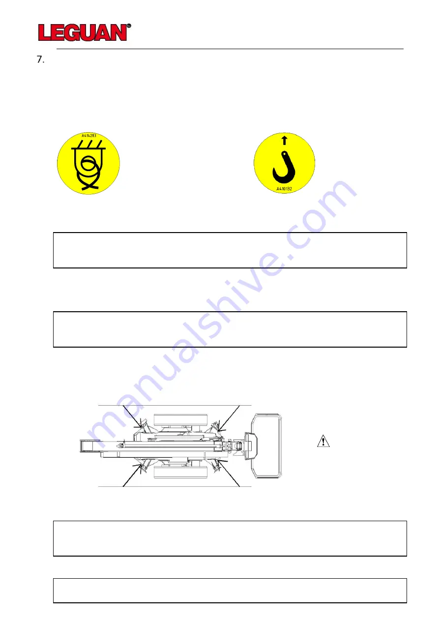
The chassis and outriggers are equipped with lifting and binding points which are indicated with
symbols. The machine may only be secured for transport from these binding points. The
machine must always be lifted from the designated lifting points. When lifting, it is advisable to
use a lifting beam to prevent the outriggers from getting damaged.
Figure 11 Binding point symbol
Figure 12 Lifting point symbol
Before transport, the booms are placed on the transport supports and the outriggers are raised.
NOTE! This access platform may only be transported in its transport
position.
No persons or materials are allowed to be transported on the platform.
There is an automatic hydraulic brake in the rear axle that engages automatically when the
combustion engine/electric motor is not running.
DO NOT TOW!
Towing can cause severe damage to the hydraulic motors and other parts
of the chassis.
If the machine is transported on a trailer, a lorry or a similar vehicle, it must be secured
carefully. There are four binding points marked on the corners of the chassis which make it easy
to secure the machine. Always secure the machine diagonally from each corner.
Figure 13 Binding locations
NOTE! Shut off the fuel faucet of the combustion engine for longer
transport to prevent motor oil and petrol from becoming mixed and causing
problems in the running of the motor.
NOTE! The machine must not be secured so that the ropes go over the
booms. Only the marked binding points can be used!
Содержание 135 NEO
Страница 1: ...Operator and Service manual Version 7 2020 July 2020 ...
Страница 9: ...9 Main dimensions Figure 2 135 NEO Main dimensions side Figure 3 135 NEO main dimensions rear ...
Страница 10: ...10 Reach diagram and support dimensions Figure 4 Reach diagram Figure 5 Support dimensions ...
Страница 59: ...59 Figure 37 Load control of the platform Figure 38 Boom position monitoring ...
Страница 60: ...60 Figure 39 Platform levelling monitoring Figure 40 Outrigger monitoring ...
Страница 61: ...61 Figure 41 Transport position monitoring Figure 42 Prevention of drive function ...
Страница 62: ...62 Figure 43 Selection of the platform control position Figure 44 Selection of the lower control position ...
Страница 63: ...63 Figure 45 Selection of the remote control position Figure 46 Platform emergency stop button override ...
Страница 64: ...64 Figure 47 Platform load monitoring override Figure 48 Override of Safety Functions ...


