
56
Warning:
Make sure that the hydraulic cylinders
of the connected implements contain the same
type of oil as the transmission unit of the tractor
to prevent this from being polluted and leading
to faulty operation.
Operation
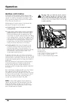
Auxiliary control valves
A maximum of three auxiliary control valves can be
mounted on the right-hand side of the hydraulic lift on
request, in order to control external cylinders. These
control valves are linked to the circuit of the hydraulic
lift and thus use the same oil.
Different types of control valve can be mounted de-
pending on the type of work involved:
Standard control valve for single and double-
acting cylinders.
Control valve with automatic release and floating
position
(available on request on certain models).
Can be selected as single or double-acting. The
control lever (A - Fig. 44) remains locked in the lifting
and lowering position. Once the ram reaches end of
stroke, the pressure automatically releases the lever
and returns it to the neutral position. You can also
manually return the lever to the neutral position
before the ram reaches the end of its stroke.
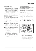
Floating position:
this mode of operation is de-
signed for implements that need constant and
automatic regulation of the work position. The
floating position is obtained by moving the lever (A)
fully forwards to second position where it will
remain locked at end of travel.
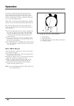
If released, the control lever (A) of the control valves
normally returns to the hold position on its own, locking
the implement in the position required. The lever can be
locked in the neutral position by setting the knob (B) to
position (2).
All control valves can be regulated to control single or
double-acting cylinders. To obtain double-acting
auxiliary control valves, knob (B) should be set to
position (1) while for single-acting operation knob (B) is
in position 3.
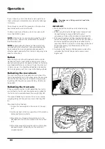
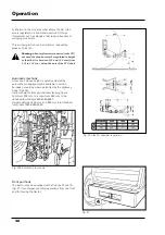
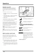
Each control valve is equipped with one or two female
half-coupling of the Push-Pull type that can be
connected to male half-couplings of any brand so long
as they are of the same size. It is very easy to connect
and detach the half-couplings: just push them to
connect and pull them to detach (Fig. 54b).
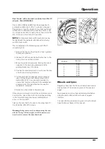
NOTE:
to ensure the hydraulic circuit operates in a
regular way, the level of the transmission oil must be
frequently checked and topped up if necessary as
indicated in the Checking the transmission oil level
part of the Maintenance chapter.
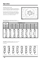
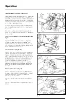
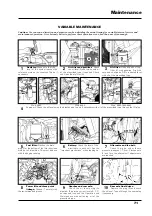
Fig. 44 - Auxiliary control valves
A Control lever
B Adjuster knob
1 Lever free for double-acting operation
2 Lever locked in neutral position
3 Lever to control single-acting cylinders
A
A
3
2
1
Содержание 5860
Страница 28: ...Safety notes 24e Page left intentionally blank...
Страница 80: ...Maintenance 76 Page left intentionally blank...
Страница 88: ...Electrical system 84 Page left intentionally blank...
Страница 111: ...107 Table of contents Page N Technical specifications 108 Routine maintenance 109 Ground speed table 109 7860HC 8860 HC...
Страница 126: ...122 To ensure long and efficient service from your tractor use only spare parts and lubricants recommended by...
Страница 132: ...123 To ensure long and efficient service from your tractor use only spare parts and lubricants recommended by...


