
53
Operation
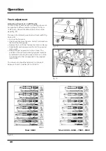
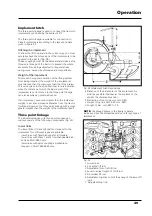
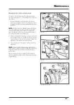
Use of the controls (Fig.38)
Move the lever (B) fully back to the position control
setting.
Make sure that the supplementary oil tap switch (E -
Fig. 48) is not engaged.
To regulate the work position of the implement, pro-
gressively move the control lever (A) downwards or
upwards until the desired position has been reached
and then lock the check nut (C) under the lever itself
to obtain the same work position on each run.
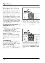
Work in draft control mode
Lift operation in draft control mode automaticaly keeps
the tractive force of the tractor at a steady rate regardless
of variations in the soil conditions.
Draft control mode is used with all mounted tractor im-
plements which do not rest on the ground (e.g.: skids,
wheels, etc.).
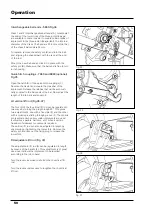
Use of the controls
(Fig. 38)
Move the lever (B) fully forwards to the draft control
position.
Make sure that the supplementary oil tap switch (E -
Fig. 39) is not engaged.
Dig the implement down the desired depth at the be-
ginning of the furrow, progressively moving the con-
trol lever (A) forwards. The depth reached by the im-
plement will be proportional to the movement of the
lever.
When the implement has reached the required depth,
lock the nut (C) in front of the control lever so that the
same depth is obtained on each run.
Move the control lever (A) back to raise the implement
at the end of each run.
Control lever travel must be very slight when working
at shallow depths.
To prevent the implement from digging into the soil
too slowly, it is advisable to move the lever fully for-
wards and the beginning of each run, by-passing lock
(C) and to then progressively move the lever back to
the desired position, by-passing lock (C) again in the
opposite direction.
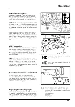
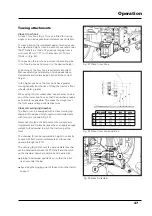
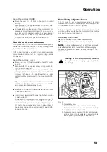
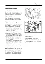
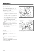
Sensitivity adjuster lever
The lift must be set to maximum sensitivity to obtain
maximum draft control. Sensitivity is adjusted by means
of the relative control lever (D - Fig, 39).
This lever must be regulated to the maximum sensitivity
position without subjecting the implement to a continu-
ous and annoying jerking action.
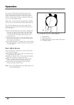
Sensitivity control lever
Turn clockwise = to increase the sensitivity.
Turn anticlockwise = to reduce the sensitivity.
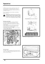
NOTE:
to increase the sensitivity of draft control mode,
place the top link in the lowest hole of the swinging
support. Less sensitivity is obtained by placing it in the
topmost hole.
Warning:
Never tow implements by connecting
the top link to the swinging support of the hy-
draulic lift.
Fig. 39
D - Sensitivity lever.
Turned clockwise (+) = increased sensitivity.
Turned anticlockwise (-) = decreased sensitivity.
E - Supplementary oil tap switch.
F - Supplementary oil tap switch to control single-
acting cylinders (only available in some markets
and depending on the type of application)
Содержание 5860
Страница 28: ...Safety notes 24e Page left intentionally blank...
Страница 80: ...Maintenance 76 Page left intentionally blank...
Страница 88: ...Electrical system 84 Page left intentionally blank...
Страница 111: ...107 Table of contents Page N Technical specifications 108 Routine maintenance 109 Ground speed table 109 7860HC 8860 HC...
Страница 126: ...122 To ensure long and efficient service from your tractor use only spare parts and lubricants recommended by...
Страница 132: ...123 To ensure long and efficient service from your tractor use only spare parts and lubricants recommended by...


