51
Operation
Adjustable top link
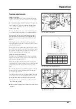
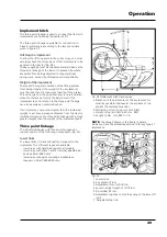
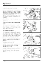
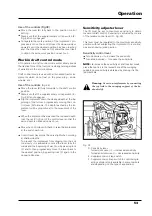
IThe adjustable top link (4 - Fig. 33) is connected to the
support by means of two holes. The correct hole to use
depends on the height of the implement.
The length of the link is varied so that the angle of the
implement can be regulated in relation to the ground.
Shorten the top link to increase the angle of attach-
ment, lengthen it to decrease the angle.
During work, the top link must slightly descend towards
the tractor, when the lower links are parallel to the
ground.
When work using lifting in draft control mode is carried
out, you must not forget that it is preferable to couple
the implement to the top hole when the towed load is
particularly heavy.
Hitching the implement
1. Allow the three point linkage to descend.
2. Adjust the top links so as to give the maximum side
play.
3. Back up the tractor.
4. Connect the coupling bar of the implement to the
ball-ends of the lower links and lock it in place with
the safety pins.
5. Adjust the length of the top links to give the imple-
ment freedom of sideways movement or lock it in
place according to the type of work required.
Important recommendations when using and
regulating the three-point linkage.
Warning:
Always stop the engine before making
any adjustments to the three point hitch or the
implement.
Warning:
Always use the lift in position control
mode when transporting implements hitched to
the three point linkage.
Warning:
Always use the lift in position control
mode when an implement is hitched or unhitched
to or from the three point linkage..
Warning:
When the tractor is stopped, always
lower any implements connected to the three
point linkage.
Warning:
Never ever work under an implement
kept raised by the hydraulic lift alone. Always
block it safely with a suitable support and turn
off the engine.
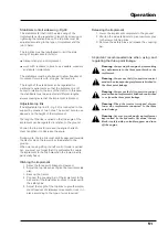
Stabilizers to limit side swing -Fig.33
The stabilizers (6) that limit the side swing of the
implements can be regulated in length by screwing or
tightening the relative sleeve. The top links must be
adjusted according to the type of implement and the
job in hand.
The top links must be lengthened to limit the side
swing of implements in order to:
transport any type of implement
work with: levellers, rollers, hoes, seeders, weeders
and similar implements.
The stabilizers must be shortened to allow freedom of
movement for work with: ploughs, harrows, etc.
The length of the stabilizers can be regulated for
particular requirements so that the implement is off-
center in relation to the axis of the tractor. In this case,
the stabilizers must be adjusted at different lengths,
always making sure that the implement is blocked.
Releasing the implement
1. Lower the implement completely to the ground.
2. Shorten the side stabilizers to give maximum play
to the lower hitching links.
3. Remove the safety pins and release the coupling
bar.
Содержание 5860
Страница 28: ...Safety notes 24e Page left intentionally blank...
Страница 80: ...Maintenance 76 Page left intentionally blank...
Страница 88: ...Electrical system 84 Page left intentionally blank...
Страница 111: ...107 Table of contents Page N Technical specifications 108 Routine maintenance 109 Ground speed table 109 7860HC 8860 HC...
Страница 126: ...122 To ensure long and efficient service from your tractor use only spare parts and lubricants recommended by...
Страница 132: ...123 To ensure long and efficient service from your tractor use only spare parts and lubricants recommended by...

