


10-S13
M8540, M9540, WSM
CABIN
5. CHECKING AND CHARGING REFRIGERANT CYCLE
[1] CHECKING WITH MANIFOLD GAUGE
IMPORTANT
Q
• The gauge indications described in the following testing are those taken under the same condition, so it
should be noted that the gauge readings will differs somewhat with the ambient conditions.
Condition
• Ambient temperature :
30 to 35 °C (86 to 95 °F)
• Engine speed : Approx.
1500 min
−
1
(rpm)
• Temperature control lever :
Maximum cooling position
• Blower switch :
HI position
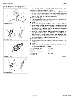
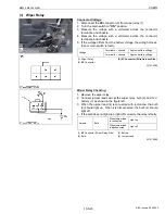
Manifold Gauge Connecting and Test Preparation
1. Close the manifold gauge
HI
and
LO
pressure side valve (3), (4)
tightly.
2. Connect the charging hose (red) (2) to the
HI
pressure side
charging valve (7) and connect the charging hose (blue) (1) to the
LO
pressure side charging valve (6).
NOTE
Q
• Be sure to drive out the air in the charging hoses at the
manifold gauge connection end by utilizing the refrigerant
pressure in the refrigerating cycle.
3. Start the engine and set at approx.
1500 min
-1
(rpm)
.
4. Turn on the A/C switch and set the temperature control dial to
maximum cooling
position.
5. Set the blower switch to
HI
position.
W1015662
Normal Operating
If the refrigerating cycle is operating normally, the reading at the
LO
pressure side (1) should be generally by around 0.15 to 0.20
MPa (1.5 to 2.0 kgf/cm
2
, 21 to 28 psi) and that at the
HI
pressure side
(2) around 1.27 to 1.66 MPa (13 to 17 kgf/cm
2
, 185 to 242 psi).
W1015870
(1) Charging Hose (Blue)
(2) Charging Hose (Red)
(3)
HI
Pressure Side Valve
(4)
LO
Pressure Side Valve
(5) Manifold Gauge
(6)
LO
Pressure Side Charging Valve
(7)
HI
Pressure Side Charging Valve
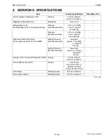
Gas pressure
Factory
spec.
Low
pressure
side
0.15 to 0.20 MPa
1.5 to 2.0 kgf/cm
2
21 to 28 psi
High
pressure
side
1.27 to 1.66 MPa
13 to 17 kgf/cm
2
185 to 242 psi
(1)
LO
Pressure Side
(2)
HI
Pressure Side
KiSC issued 09, 2008 A
Содержание M9540
Страница 1: ...M8540 M9540 WORKSHOP MANUAL TRACTOR KiSC issued 09 2008 A...
Страница 8: ...6 M8540 M9540 WSM SAFETY INSTRUCTIONS KiSC issued 09 2008 A...
Страница 9: ...7 M8540 M9540 WSM SAFETY INSTRUCTIONS KiSC issued 09 2008 A...
Страница 10: ...8 M8540 M9540 WSM SAFETY INSTRUCTIONS Q CABIN Model KiSC issued 09 2008 A...
Страница 11: ...9 M8540 M9540 WSM SAFETY INSTRUCTIONS KiSC issued 09 2008 A...
Страница 12: ...10 M8540 M9540 WSM SAFETY INSTRUCTIONS KiSC issued 09 2008 A...
Страница 16: ...14 M8540 M9540 WSM DIMENSIONS DIMENSIONS ROPS Model KiSC issued 09 2008 A...
Страница 17: ...15 M8540 M9540 WSM DIMENSIONS CABIN Model KiSC issued 09 2008 A...
Страница 18: ...G GENERAL KiSC issued 09 2008 A...
Страница 103: ...1 ENGINE KiSC issued 09 2008 A...
Страница 203: ...2 CLUTCH KiSC issued 09 2008 A...
Страница 219: ...3 TRANSMISSION KiSC issued 09 2008 A...
Страница 322: ...4 REAR AXLE KiSC issued 09 2008 A...
Страница 323: ...CONTENTS MECHANISM 1 FEATURES 4 M1 KiSC issued 09 2008 A...
Страница 336: ...5 BRAKES KiSC issued 09 2008 A...
Страница 374: ...6 FRONT AXLE KiSC issued 09 2008 A...
Страница 375: ...CONTENTS MECHANISM 1 STRUCTURE 6 M1 1 FRONT AXLE 6 M1 2 LIMITED SLIP DIFFERENTIAL LSD 6 M2 KiSC issued 09 2008 A...
Страница 401: ...7 STEERING KiSC issued 09 2008 A...
Страница 402: ...CONTENTS MECHANISM 1 STEERING MECHANISM 7 M1 2 STEERING CYLINDER 7 M2 KiSC issued 09 2008 A...
Страница 420: ...8 HYDRAULIC SYSTEM KiSC issued 09 2008 A...
Страница 473: ...9 ELECTRICAL SYSTEM KiSC issued 09 2008 A...
Страница 554: ...10 CABIN KiSC issued 09 2008 A...