


1-S42
M8540, M9540, WSM
ENGINE
Selecting Cylinder Head Gasket
Q
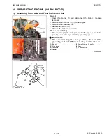
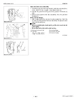
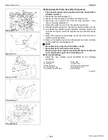
Replacing the Cylinder Head Gasket
1. Make sure to note the notch
(a)
,
(b)
or
(c)
of cylinder head gasket
(1) in advance.
2. Replace the same notch
(a)
,
(b)
or
(c)
as the original cylinder
head gasket (1).
Q
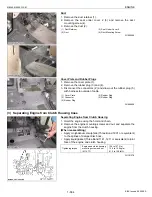
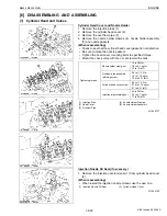
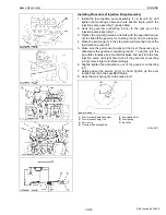
Selecting the Cylinder Head Gasket
• Select the cylinder head gasket (1) thickness to meet with the top
clearance when replacing the piston, piston pin bush, connecting
rod or crankpin bearing.
1. Measure the piston head’s protrusion or recessing from the
crankcase cylinder face 4 spots per each piston and (average of
four pistons) using the dial gauge as shown in figure.
2. Select the suitable cylinder head gasket refer to the table below.
W1022965
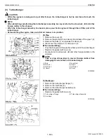
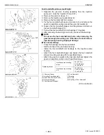
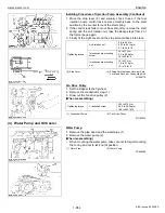
Valve
1. Remove the valve spring collets (1) after compressing the valve
spring (3) with the valve spring retainer (2).
(When reassembling)
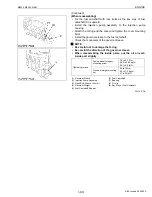
• Install the valve spring with its small-pitch end downward (at the
head side).
• Wash the valve stem and valve guide hole, and apply engine oil
sufficiently.
• After installing the valve spring collets, lightly tap the stem to
assure proper fit with a plastic hammer.
W1053044
Notch of
Cylinder
Head
Gasket
Thickness of cylinder
head gasket
Part Code
Piston Head’s
protrusion or
recessing from the
level of crankcase
cylinder face.
(average of 4 pistons)
Before
tightening
After
tightening
2 notches
(a)
0.90 mm
0.035 in.
0.80 mm
0.031 in.
1G514-03310
-0.07 to +0.049 mm
-0.0028 to +0.0019 in.
1 notch
(b)
1.00 mm
0.0394 in.
0.90 mm
0.035 in.
1G514-03600
+0.050 to +0.149 mm
+0.0020 to +0.0058 in.
Without
notch
(c)
1.05 mm
0.0413 in.
0.95 mm
0.037 in.
1G514-03610
+0.150 to +0.20 mm
+0.0059 to +0.0078 in.
(1) Cylinder Head Gasket
(2) Measuring Point
(A) Gear Case Side
(B) Flywheel Side
(a) 2 Notches
(b) 1 Notch
(c) Without Notch
(1) Valve Spring Collet
(2) Valve Spring Retainer
(3) Valve Spring
(4) Valve Stem Seal
(5) Valve
(6) Arm Bridge
(7) Large Pitch
(8) Smaller Pitch
(9) Install the spring with its smaller-
pitch end downward (at the head
side)
KiSC issued 09, 2008 A
Содержание M9540
Страница 1: ...M8540 M9540 WORKSHOP MANUAL TRACTOR KiSC issued 09 2008 A...
Страница 8: ...6 M8540 M9540 WSM SAFETY INSTRUCTIONS KiSC issued 09 2008 A...
Страница 9: ...7 M8540 M9540 WSM SAFETY INSTRUCTIONS KiSC issued 09 2008 A...
Страница 10: ...8 M8540 M9540 WSM SAFETY INSTRUCTIONS Q CABIN Model KiSC issued 09 2008 A...
Страница 11: ...9 M8540 M9540 WSM SAFETY INSTRUCTIONS KiSC issued 09 2008 A...
Страница 12: ...10 M8540 M9540 WSM SAFETY INSTRUCTIONS KiSC issued 09 2008 A...
Страница 16: ...14 M8540 M9540 WSM DIMENSIONS DIMENSIONS ROPS Model KiSC issued 09 2008 A...
Страница 17: ...15 M8540 M9540 WSM DIMENSIONS CABIN Model KiSC issued 09 2008 A...
Страница 18: ...G GENERAL KiSC issued 09 2008 A...
Страница 103: ...1 ENGINE KiSC issued 09 2008 A...
Страница 203: ...2 CLUTCH KiSC issued 09 2008 A...
Страница 219: ...3 TRANSMISSION KiSC issued 09 2008 A...
Страница 322: ...4 REAR AXLE KiSC issued 09 2008 A...
Страница 323: ...CONTENTS MECHANISM 1 FEATURES 4 M1 KiSC issued 09 2008 A...
Страница 336: ...5 BRAKES KiSC issued 09 2008 A...
Страница 374: ...6 FRONT AXLE KiSC issued 09 2008 A...
Страница 375: ...CONTENTS MECHANISM 1 STRUCTURE 6 M1 1 FRONT AXLE 6 M1 2 LIMITED SLIP DIFFERENTIAL LSD 6 M2 KiSC issued 09 2008 A...
Страница 401: ...7 STEERING KiSC issued 09 2008 A...
Страница 402: ...CONTENTS MECHANISM 1 STEERING MECHANISM 7 M1 2 STEERING CYLINDER 7 M2 KiSC issued 09 2008 A...
Страница 420: ...8 HYDRAULIC SYSTEM KiSC issued 09 2008 A...
Страница 473: ...9 ELECTRICAL SYSTEM KiSC issued 09 2008 A...
Страница 554: ...10 CABIN KiSC issued 09 2008 A...