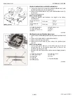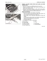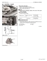
8-S21
M8540, M9540, WSM
HYDRAULIC SYSTEM
[2] 3-POINT HITCH HYDRAULIC BLOCK ASSEMBLY
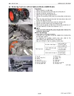
(1) Removing Top Cover (3-Point Hitch Hydraulic Block) (ROPS Model)
Preparation 1
1. Remove the lower links (2) and lift rods (1).
2. Disconnect the connector (3) for trailer coupler then remove the
top link holder (8) with trailer coupler.
3. Disconnect the auxiliary control valve wire (6).
4. Disconnect the cylinder hose (12) from hydraulic cylinder.
5. Remove the hydraulic cylinder cover (9).
6. Disconnect the breather hose (11) from hydraulic cylinder.
7. Remove the cylinder pin (upper) (13).
8. Remove the cylinder pin (lower) (10), then take out the cylinder.
9. Remove the top link (7).
10.Remove the delivery pipe (4).
11.Disconnect the position control rod (16) from the position lever 1
(17) and draft control rod (15) from the draft lever 1 (14).
12.Remove the auxiliary control valve (5).
13.Disconnect the ground harness (19).
14.Disconnect the lowering speed rod (18).
NOTE
Q
• Take care not to damage the grease nipple when remove the
hydraulic cylinder pin.
(When reassembling)
• Apply grease to the grease nipples.
• Take care not to damage the grease nipples when reassemble
the hydraulic cylinder.
• To assemble the auxiliary control valve wire, refer to “[1]
CHECKING AND ADJUSTING” in this section.
• Be sure to fit the O-rings for auxiliary control valve.
W1018551
Tightening torque
3-point hitch delivery pipe
retaining nut
107.9 to 117.7 N·m
11.0 to 12.0 kgf·m
79.6 to 86.8 lbf·ft
Cylinder hose retaining nut
45.1 to 53.0 N·m
4.6 to 5.4 kgf·m
33.3 to 39.1 lbf·ft
(1) Lift Rod
(2) Lower Link
(3) Connector
(4) Delivery Pipe
(5) Auxiliary Control Valve
(6) Auxiliary Control Valve Wire
(7) Top Link
(8) Top Link Holder
(9) Hydraulic Cylinder Cover
(10) Cylinder Pin (Lower)
(11) Breather Hose
(12) Cylinder Hose
(13) Cylinder Pin (Upper)
(14) Draft Lever 1
(15) Draft Control Rod
(16) Position Control Rod
(17) Position Lever 1
(18) Lowering Speed Rod
(19) Ground Harness
KiSC issued 09, 2008 A
Содержание M9540
Страница 1: ...M8540 M9540 WORKSHOP MANUAL TRACTOR KiSC issued 09 2008 A...
Страница 8: ...6 M8540 M9540 WSM SAFETY INSTRUCTIONS KiSC issued 09 2008 A...
Страница 9: ...7 M8540 M9540 WSM SAFETY INSTRUCTIONS KiSC issued 09 2008 A...
Страница 10: ...8 M8540 M9540 WSM SAFETY INSTRUCTIONS Q CABIN Model KiSC issued 09 2008 A...
Страница 11: ...9 M8540 M9540 WSM SAFETY INSTRUCTIONS KiSC issued 09 2008 A...
Страница 12: ...10 M8540 M9540 WSM SAFETY INSTRUCTIONS KiSC issued 09 2008 A...
Страница 16: ...14 M8540 M9540 WSM DIMENSIONS DIMENSIONS ROPS Model KiSC issued 09 2008 A...
Страница 17: ...15 M8540 M9540 WSM DIMENSIONS CABIN Model KiSC issued 09 2008 A...
Страница 18: ...G GENERAL KiSC issued 09 2008 A...
Страница 103: ...1 ENGINE KiSC issued 09 2008 A...
Страница 203: ...2 CLUTCH KiSC issued 09 2008 A...
Страница 219: ...3 TRANSMISSION KiSC issued 09 2008 A...
Страница 322: ...4 REAR AXLE KiSC issued 09 2008 A...
Страница 323: ...CONTENTS MECHANISM 1 FEATURES 4 M1 KiSC issued 09 2008 A...
Страница 336: ...5 BRAKES KiSC issued 09 2008 A...
Страница 374: ...6 FRONT AXLE KiSC issued 09 2008 A...
Страница 375: ...CONTENTS MECHANISM 1 STRUCTURE 6 M1 1 FRONT AXLE 6 M1 2 LIMITED SLIP DIFFERENTIAL LSD 6 M2 KiSC issued 09 2008 A...
Страница 401: ...7 STEERING KiSC issued 09 2008 A...
Страница 402: ...CONTENTS MECHANISM 1 STEERING MECHANISM 7 M1 2 STEERING CYLINDER 7 M2 KiSC issued 09 2008 A...
Страница 420: ...8 HYDRAULIC SYSTEM KiSC issued 09 2008 A...
Страница 473: ...9 ELECTRICAL SYSTEM KiSC issued 09 2008 A...
Страница 554: ...10 CABIN KiSC issued 09 2008 A...


