background image

G-20

M8540, M9540, WSM

G  

GENERAL

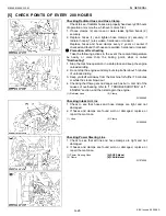
Changing Transmission Fluid

CAUTION

• Allow engine to cool down sufficiently, oil can be hot and

can burn.

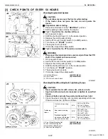
1. To drain the used oil, remove the drain plug (1) at the bottom of

the transmission case and drain the oil completely into the oil
pan.

2. After draining reinstall the drain plug.
3. Fill with the new KUBOTA SUPER UDT fluid up to the upper

notch on the dipstick (2).

4. (Refer to “4. LUBRICANTS, FUEL AND COOLANT” in this

section.)

5. After running the engine for a few minutes, stop it and check the

oil level again; add oil to prescribed level.

IMPORTANT

Q

• Do not operate the tractor immediately after changing the

transmission fluid.
Run the engine at medium speed for a few minutes to
prevent damage to the transmission.

W1022400

Changing Front Differential Case Oil

1. To drain the used oil, remove the drain and filling plug at the front

differential case and drain the oil completely into the oil pan.

2. After draining reinstall the drain plug (1).
3. Remove the oil level check plug (3).
4. Fill with the new oil up to the lower rim of check plug port (3).

(Refer to “4. LUBRICANTS, FUEL AND COOLANT” in this
section.) 

5. After filling reinstall the filling plug and check plugs.

W1063019

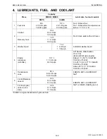
Oil capacity

60 L
63.4 U.S.qts.
52.8 Imp.qts.

(1) Drain Plug
(2) Dipstick
(3) Oil Inlet

(A) Oil level is acceptable within the 

range.

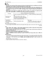
Oil capacity

6.0 L
6.3 U.S.qts.
5.3 Imp.qts.

(1) Drain Plug
(2) Filling Port

(3) Check Plug

KiSC issued 09, 2008 A

Содержание M9540

Страница 1: ...M8540 M9540 WORKSHOP MANUAL TRACTOR KiSC issued 09 2008 A...

Страница 2: ...Mechanism Workshop Manual Code No 9Y021 01874 9Y021 18201 for the one which has not been described to this workshop manual Q Servicing Information on the troubleshooting servicing specification lists...

Страница 3: ...al and on labels on the machine itself to warn of the possibility of personal injury Read these instructions carefully It is essential that you read the instructions and safety regulations before you...

Страница 4: ...support the machine by safety stands Do not touch the rotating or hot parts while the engine is running Never remove the radiator cap while the engine is running or immediately after stopping Otherwi...

Страница 5: ...st be running to do some work make sure the area is well ventilated Never run the engine in a closed area The exhaust gas contains poisonous carbon monoxide PREVENT ACID BURNS Sulfuric acid in battery...

Страница 6: ...INSTRUCTIONS PREPARE FOR EMERGENCIES Keep a first aid kit and fire extinguisher handy at all times Keep emergency numbers for doctors ambulance service hospital and fire department near your telephon...

Страница 7: ...lowing safety decals pictorial safety labels are installed on the machine If a decal becomes damaged illegible or is not on the machine replace it The decal part number is listed in the parts list Q R...

Страница 8: ...6 M8540 M9540 WSM SAFETY INSTRUCTIONS KiSC issued 09 2008 A...

Страница 9: ...7 M8540 M9540 WSM SAFETY INSTRUCTIONS KiSC issued 09 2008 A...

Страница 10: ...8 M8540 M9540 WSM SAFETY INSTRUCTIONS Q CABIN Model KiSC issued 09 2008 A...

Страница 11: ...9 M8540 M9540 WSM SAFETY INSTRUCTIONS KiSC issued 09 2008 A...

Страница 12: ...10 M8540 M9540 WSM SAFETY INSTRUCTIONS KiSC issued 09 2008 A...

Страница 13: ...del 2560 mm 100 8 in CABIN Model 2650 mm 104 3 in Wheel base 2250 mm 88 6 in Tread Front 1514 1554 1608 mm 59 61 61 18 63 31 in Rear 1503 1599 1695 mm 59 17 62 95 66 73 in Minimum ground clearance ROP...

Страница 14: ...0 43 0 27 0 46 0 29 0 39 0 24 2 0 55 0 34 0 59 0 37 0 50 0 31 3 0 73 0 45 0 78 0 48 0 65 0 40 4 0 94 0 58 0 99 0 62 0 84 0 52 5 1 16 0 721 1 23 0 764 1 04 0 646 6 1 44 0 895 1 48 0 920 1 25 0 777 L 1...

Страница 15: ...0 46 0 29 0 39 0 24 2 0 55 0 34 0 60 0 37 0 50 0 31 3 0 73 0 45 0 79 0 49 0 66 0 41 4 0 93 0 58 1 01 0 628 0 85 0 53 5 1 15 0 715 1 25 0 777 1 05 0 652 6 1 43 0 889 1 50 0 932 1 26 0 783 L 1 2 8 1 7...

Страница 16: ...14 M8540 M9540 WSM DIMENSIONS DIMENSIONS ROPS Model KiSC issued 09 2008 A...

Страница 17: ...15 M8540 M9540 WSM DIMENSIONS CABIN Model KiSC issued 09 2008 A...

Страница 18: ...G GENERAL KiSC issued 09 2008 A...

Страница 19: ...URS G 22 4 CHECK POINTS OF EVERY 100 HOURS G 23 5 CHECK POINTS OF EVERY 200 HOURS G 28 6 CHECK POINTS OF EVERY 300 HOURS G 31 7 CHECK POINTS OF EVERY 400 HOURS G 32 8 CHECK POINTS OF EVERY 600 HOURS G...

Страница 20: ...ng your local KUBOTA distributor always specify engine serial number tractor serial number and hourmeter reading W1010800 1 Tractor Identification Plate 2 Tractor Serial Number 3 Engine Serial Number...

Страница 21: ...Year Alphabet or Number Year 1 2001 F 2015 2 2002 G 2016 3 2003 H 2017 4 2004 J 2018 5 2005 K 2019 6 2006 L 2020 7 2007 M 2021 8 2008 N 2022 9 2009 P 2023 A 2010 R 2024 B 2011 S 2025 C 2012 T 2026 D...

Страница 22: ...le E2 engines may result in emission levels out of compliance with the original E3 design and EPA or other applicable regulations Please refer to the emission label located on the engine head cover to...

Страница 23: ...only KUBOTA genuine parts for parts replacement to maintain machine performance and to assure safety Gaskets and O rings must be replaced during reassembly Apply grease to new O rings or oil seals bef...

Страница 24: ...c check for a fee Do not attempt to modify or remodel any electrical parts and wiring When removing the battery cables disconnect the negative cable first When installing the battery cables connect th...

Страница 25: ...re sag be required W1011587 In installing a part take care not to get wiring caught by it W1011670 After installing wiring check protection of terminals and clamped condition of wiring only connect ba...

Страница 26: ...Before recharging the battery remove it from the machine Before recharging remove cell caps Do recharging in a well ventilated place where there is no open flame nearby as hydrogen gas and oxygen are...

Страница 27: ...there is no female connector being too open W1012430 Make certain plastic cover is large enough to cover whole connector W1012519 5 HANDLING OF CIRCUIT TESTER Use tester correctly following manual pro...

Страница 28: ...U S qts 0 9 Imp qts 3 Washer liquid 1 3 L 1 4 U S qts 1 1 Imp qts Automobil washer liquid 4 Engine crankcase with filter 10 7 L 11 3 U S qts 9 4 Imp qts API Service Classification CF or CI 4 External...

Страница 29: ...case support 2 Until grease overflows Multipurpose NLGI 2 or NLGI 1 GC LB grease Front axle support 2 Top link 1 Top link bracket 2 Lift rod 2 Hydraulic lift cylinder pin 4 Steering joint shaft CABIN...

Страница 30: ...n 0 5 sulfur content is used reduce the service interval for engine oil and filter by 50 DO NOT use diesel fuel with sulfur content greater than 1 0 Diesel fuels specified to EN 590 or ASTM D975 are r...

Страница 31: ...2 39 2 to 44 1 4 0 to 4 5 28 9 to 32 5 60 8 to 70 5 6 2 to 7 2 44 9 to 52 1 M12 12 mm 0 47 in 62 8 to 72 5 6 4 to 7 4 46 3 to 53 5 77 5 to 90 1 7 9 to 9 2 57 2 to 66 5 62 8 to 72 5 6 4 to 7 4 46 3 to...

Страница 32: ...0 to 7 0 36 1 to 50 6 15 t1 6 107 9 to 117 7 11 0 to 12 0 79 6 to 86 8 18 t1 6 107 9 to 117 7 11 0 to 12 0 79 6 to 86 8 Items Thread size Tightening torque N m kgf m lbf ft POA PF Nipple with O ring P...

Страница 33: ...every 100 Hr 1 G 25 Replace every 1 year 2 G 25 Secondary element Replace every 1 year G 25 8 Fuel line Check every 100 Hr G 26 Replace every 2 years G 26 9 Parking brake lever Adjust every 100 Hr G...

Страница 34: ...every 800 Hr G 33 26 Fuel injection nozzle injection pressure Check every 1500 Hr G 33 27 Turbocharger Check every 3000 Hr G 34 28 Injection pump Check every 3000 Hr G 34 29 Intake air heater Check ev...

Страница 35: ...on by reading the indicator annually W1025390 No Item Service Interval Since then Impor tant Refe rence page 50 100 150 200 250 300 350 400 450 500 550 600 650 700 1 Inner air filter Clean every 200 H...

Страница 36: ...and clean the radiator screen grill oil cooler and battery mount 12 Check and clean the air conditioner condenser screen CABIN model 13 Check the nuts of tires are tight 14 Check the number plate for...

Страница 37: ...ngine before changing oil filter cartridge Allow engine to cool down sufficiently oil can be hot and can burn 1 Remove the oil filter 1 2 Put a film of clean engine oil on rubber seal of new filter 3...

Страница 38: ...the filter quickly until it contacts the mounting surface Tighten filter by hand and additional 1 2 turn only 7 After the new filter has been replaced fill with the oil up to the upper notch on the di...

Страница 39: ...ely after changing the transmission fluid Run the engine at medium speed for a few minutes to prevent damage to the transmission W1022400 Changing Front Differential Case Oil 1 To drain the used oil r...

Страница 40: ...After draining reinstall the drain plugs 3 Fill with the new oil up to the filling plug port Refer to 4 LUBRICANTS FUEL AND COOLANT in this section 4 After filling reinstall the filling plugs 2 NOTE...

Страница 41: ...the clutch pedal 2 fully 4 Shift the shuttle shift lever 1 to the neutral position 5 Turn the key to START position 6 The engine must not crank 7 If it cranks inspect the safety switch W1062967 Checki...

Страница 42: ...e grease to following points every 100 hours 2 If you operated the machine in extremely wet and muddy condition lubricate grease fittings more often To be continued 1 Battery Terminals 2 Grease Fittin...

Страница 43: ...GENERAL Continued W1025259 5 Grease Fitting Top Link Bracket 6 Grease Fitting Lifting Rod 7 Grease Fitting Top Link 8 Grease Fitting Hydraulic Lift Cylinders Pin 9 Steering Joint Shaft A CABIN Model...

Страница 44: ...it is damaged or not 3 Replace the primary element 2 Once a year or after every six times of cleaning whichever comes first IMPORTANT Q The air cleaner uses a dry element never apply oil Do not run t...

Страница 45: ...bleed the fuel system Refer to 14 OTHERS in this section W1067279 Adjusting Brake Pedal 1 To check and adjusting for brake pedal refer to 1 CHECKING AND ADJUSTING at 5 BRAKES section W1025046 Adjustin...

Страница 46: ...eum jelly 3 Check the battery condition by reading the indicator W1024321 Directions for Storage CAUTION When connecting the battery do not reverse the polarities Connection with reverse polarities wi...

Страница 47: ...n in a safe place and keep the engine unloaded idling 2 Do not stop the engine suddenly but stop it after about 5 minutes of unloaded idling 3 Keep yourself well away from the machine for further 10 m...

Страница 48: ...ach the snap ring 1 of the tie rod joint W1026029 Draining Fuel Tank Water 1 Loosen the drain plug 2 at the bottom of the fuel tank 1 to let sediments impurities and water out of the tank Finally tigh...

Страница 49: ...flow NOTE Q If the filter is very dirty Dip the filter in lukewarm water with mild dish washing detergent Move it up and down as well as left and right to loosen dirt Rinse the filter with clean wate...

Страница 50: ...9 Adjusting Air Conditioner Belt Tension CABIN Model CAUTION Be sure to stop the engine before checking belt tension 1 Push on the belt between the pulleys with a finger under 9 8 N 10 kgf 22 lbf load...

Страница 51: ...ction W1026760 Cleaning Water Separator This job should not be done in the field but in a clean place 1 Close the fuel cock 1 2 Unscrew the retainer ring 2 and remove the cup 3 and rinse the inside wi...

Страница 52: ...front axle pivot pin adjustment is not correct front wheel vibration can occur causing vibration in the steering wheel Q Adjusting Procedure 1 Loosen the lock nut 2 screw in the adjusting screw 1 unti...

Страница 53: ...NG at 9 ELECTRICAL SYSTEM section W1074973 12 CHECK POINTS OF EVERY 1 YEAR Replacing Air Cleaner Primary Element and Secondary Element 1 Refer to 4 CHECK POINTS OF EVERY 100 HOURS in this section W102...

Страница 54: ...nd anti freeze until the coolant level is just below the radiator cap Install the radiator cap 3 securely 7 Fill with clean water and anti freeze up to the upper line of recovery tank 4 8 Start and op...

Страница 55: ...ore a long term storage let out coolant completely or mix fresh water with long life coolant and fill the radiator and reserve tank with the mixture 1 Long life coolant hereafter LLC comes in several...

Страница 56: ...ry standards that necessitate a minimum glycol content in the concentrated anti freeze When the coolant level drops due to evaporation add water only to keep the antifreeze mixing ratio less than 50 I...

Страница 57: ...HECKING DISASSEMBLING AND SERVICING at 5 BRAKES section W1079117 Replacing Equalizer Kit 1 To check and adjusting for brake pedal refer to 4 CHECKING DISASSEMBLING AND SERVICING at 5 BRAKES section W1...

Страница 58: ...ot start try it several times at 30 second intervals 4 Accelerate the engine to remove the small portion of air left in the fuel system 5 If air still remains and the engine stops repeat the above ste...

Страница 59: ...lb 5 4 Replace with a new bulb and reinstall the head lamp assembly in the reverse order Q Other lights 1 Detach the lens and replace the bulb IMPORTANT Q Be sure to use a new bulb of the specified wa...

Страница 60: ...nt of refrigerant is extremely low inspect and charge Refer to 4 Checking Charge Refrigerant Amount at 10 CABIN section Q Checking Procedure 1 Run the air conditioner in the following conditions Engin...

Страница 61: ...n Use to measure diesel engine compression and diagnostics of need for major overhaul W10242000 Oil Pressure Tester Code No 07916 32032 Application Use to measure lubricating oil pressure W10243180 1...

Страница 62: ...Material Steel E Hex nut 27 mm 1 06 in across the plat F Adhesive application G Fillet welding on the enter circumference H Retaining nut I 17 mm dia 0 67 in dia J 8 mm dia 0 31 in dia K 1 0 mm 0 039...

Страница 63: ...a 6 3 m 0 00025 in b 6 3 m 0 00025 in C1 Chamfer 1 0 mm 0 039 in C2 Chamfer 2 0 mm 0 079 in A 157 mm 6 1811 in B 14 5 mm 0 571 in C 120 mm 4 7244 in D 30 0 mm dia 1 1811 in dia E 42 000 mm dia 1 6535...

Страница 64: ...I 57 9 to 58 1 mm dia 2 2795 to 2 2874 in dia J 79 5 mm dia 3 1299 in dia K 87 mm dia 3 452 in dia L 12 mm 0 4724 in M 40 mm 1 5748 in N 120 mm 4 7244 in A 20 mm dia 0 79 in dia B 11 7 to 11 9 mm dia...

Страница 65: ...0 4724 in F 7 9 to 8 1 mm 0 3110 to 0 3189 in G 20 mm 0 0787 in H 130 mm dia 5 1181 in dia I 99 4 to 99 6 mm dia 3 9134 to 3 9213 in dia J 95 05 to 95 20 mm dia 3 7421 to 3 7480 in dia K 3 mm dia 0 11...

Страница 66: ...1 61 in dia P 32 mm dia 1 26 in dia Q 33 961 to 34 0 mm dia 1 3370 to 1 3386 in dia R 18 mm dia 0 71 in dia S 19 967 to 20 0 mm dia 0 7861 to 0 7874 in dia U 3 mm 0 12 in V 149 1 to 149 4 mm 5 8701 t...

Страница 67: ...94 in dia G 50 421 to 50 44 mm dia 1 9851 to 1 9858 in dia H 8 mm 0 31 in I 2 mm 0 08 in J 35 mm 1 38 in K 5 mm 0 20 in L 0 26 rad 15 A 35 mm 1 38 in B 33 mm 1 30 in C Chamfer 0 5 mm 0 02 in D 1 mm 0...

Страница 68: ...et W1037894 No Name of Part Q ty 1 Bracket 1 2 Flange Nut 1 3 Washer 1 4 Shaft 1 5 Piece 1 1 6 Clevis 1 7 Washer 1 8 Cotter Pin 1 9 Joint 1 1 10 Piece 2 1 11 Joint 2 1 12 Piece 3 1 a Tool 3 b Tool 4 c...

Страница 69: ...m 2 76 in O 19 5 mm 0 77 in P 12 mm 0 47 in Q 0 8 mm 0 03 in R 6 mm 0 24 in A 26 mm 1 02 in B 18 mm 0 71 in C 16 5 to 17 0 mm 0 6496 to 0 6693 in D 1 5 mm 0 06 in E 54 0 to 54 2 mm dia 2 1260 to 2 133...

Страница 70: ...693 in D 1 5 mm 0 06 in E 53 5 to 53 7 mm dia 2 1063 to 2 1142 in dia F 50 05 to 50 25 mm dia 1 9705 to 1 9783 in dia G 16 mm 0 63 in H Chamfer 1 mm 0 04 in I 8 5 mm dia 0 33 in dia J 0 4 mm 0 0157 in...

Страница 71: ...04 in I 8 5 mm dia 0 33 in dia J 0 4 mm 0 0157 in K 3 mm 0 12 in L 19 mm 0 75 in M Chamfer 0 5 mm 0 02 in N 36 mm 1 42 in O 45 mm dia 1 77 in dia P 0 78 rad 45 Q 11 5 mm 0 45 in A 480 mm 18 90 in B 50...

Страница 72: ...ss than 3 mm Less than 0 1 in I M14 x Pitch 1 5 J 0 52 rad 30 K 32 mm 1 3 in L M14 x Pitch 1 5 M 45 mm 1 8 in N 30 mm 1 2 in O 15 mm 0 59 in P 0 8 mm radius 0 03 in radius Q Chamfer 1 mm 0 04 in R Les...

Страница 73: ...1 6 to 12 1 mm 0 4567 to 0 4764 in a 14 94 to 15 mm dia 0 5882 to 0 5906 in dia J 6 to 6 1 mm 0 2362 to 0 2402 in b 55 mm 2 1654 in K 13 mm dia 0 5118 in dia c 66 mm 2 5984 in L 11 mm 0 4331 in d 100...

Страница 74: ...in H C0 2 mm 0 0079 in I R8 mm 0 3150 in J 1 mm 0 0394 in K 1 mm 0 0394 in L C0 2 mm 0 0079 in M C0 2 mm 0 0079 in N 29 mm 1 1417 in O 6 mm 0 2362 in P 10 7 mm 0 4213 in Q 35 mm 1 3780 in R 99 3 mm 3...

Страница 75: ...ion Use for aligning the crankcase 1 and 2 W1047882 A 115 mm 4 53 in B 56 mm 2 2 in C 17 mm 0 67 in D 20 mm 0 79 in E 14 mm dia 0 55 in dia F 11 mm dia 0 43 in dia G 14 mm dia 0 55 in dia H 17 5 mm 0...

Страница 76: ...Application This allows easy testing of hydraulic system W10313180 Adaptor Set for Flow Meter Code No 07916 54031 Application Use for testing the hydraulic system W10313960 1 Gauge 07916 50322 2 Cabl...

Страница 77: ...rake Air Bleeder Code No 07916 54001 Application This allows easy air bleed of the hydraulic brake W10516480 Relief Valve Setting Pressure Adaptor G Code No 07916 52751 Application This offers easy me...

Страница 78: ...lowing special tools are not provided make them referring to the figure Front Axle Rocking Restrictor W10545380 A 120 mm 4 72 in B 12 mm 0 72 in C M10 P1 25 D 30 mm 1 18 in E M16 P1 5 F 10 mm 0 39 in...

Страница 79: ...mm dia 0 57 in dia C 60 mm dia 2 36 in dia D Chamfer 5 mm 0 20 in E M14 x P1 5 F 25 mm 0 98 in G 40 mm 1 57 in H 450 mm 17 72 in I 14 mm dia 0 55 in dia J 50 mm dia 1 97 in dia K M14 x P1 5 L 10 mm 0...

Страница 80: ...0 976 in dia B 131 85 to 132 15 mm 5 19 to 5 20 in C 99 25 to 100 75 mm 3 91 to 3 97 in D 54 to 60 mm full spline 2 12 to 2 36 in full spline E 22 4 to 28 4 mm 0 88 to 1 11 in F 4 to 6 mm 0 16 to 0 2...

Страница 81: ...n B 40 mm 1 6 in C 16 mm 0 63 in D 8 mm 0 3 in E 16 mm 0 63 in F 5 2 mm dia 0 20 in dia G 5 70 to 5 90 mm 0 225 to 0 232 in H 80 mm 3 1 in A M5 x P1 0 x 12 mm depth 0 47 in depth B 19 mm 0 75 in C 5 m...

Страница 82: ...35 mm 1 4 in M Chamfer 0 5 mm 0 02 in F Radius 5 mm 0 2 in N 7 mm 0 3 in G 10 00 to 10 27 mm 0 3937 to 0 4043 in O 20 mm 0 79 in H 20 mm 0 79 in X X X View direction A 330 mm 13 0 in G 6 00 to 6 58 m...

Страница 83: ...0 78 rad 45 L 10 mm 0 39 in M 50 mm 1 97 in N 55 mm 2 17 in O 25 mm 0 97 in P 80 mm 3 15 in A 12 75 to 12 90 mm square 0 50 to 0 51 in square B 32 500 to 32 525 mm dia 1 2795 to 1 2805 in dia C 35 mm...

Страница 84: ...l W1062519 A 54 85 to 54 95 mm 2 159 to 2 163 in B 11 mm 0 43 in C 60 mm 2 36 in D 30 mm 1 18 in E 48 85 to 48 95 mm 1 923 to 1 927 in F 78 mm dia 3 07 in dia G 40 mm dia 1 57 in dia H 50 mm 1 97 in I...

Страница 85: ...ad 9 0 C 60 18 mm 2 369 in 65 18 mm 2 566 in 75 18 mm 2 960 in D 61 18 mm 2 409 in 66 18 mm 2 606 in 76 18 mm 2 999 in E 42 mm 1 7 in 42 mm 1 7 in 42 mm 1 7 in F 10 mm 0 39 in 10 mm 0 39 in 10 mm 0 39...

Страница 86: ...n dia C 35 mm 13 8 in P 1 05 rad 60 D 23 to 23 3 mm 0 9055 to 0 9713 in Q 3 mm dia 1 18 in dia E 16 mm 0 63 in R 36 mm 1 18 in F 40 mm dia 1 58 in dia S 60 mm 2 36 in G 32 4 to 32 7 mm dia 1 2756 to 1...

Страница 87: ...d dual hi lo valve W1039227 A 50 mm 2 0 in H 16 5 mm 0 650 in N 7 5 mm dia 0 30 in dia B 22 mm 0 87 in I M18 P1 5 O 1 0 rad 60 C 13 mm 0 51 in J 0 79 rad 45 P 5 mm 0 2 in D 15 mm 0 59 in K 2 5 mm 0 03...

Страница 88: ...nkage A 18 mm 0 71 in G PS 1 4 M 4 mm 0 16 in B 15 mm 0 59 in H M7 x P1 0 N 2 mm 0 079 in C 15 mm 0 59 in I 0 79 rad 45 O 2 mm dia 0 079 in dia D 3 mm 0 12 in J 0 79 rad 45 P 5 mm dia 0 20 in dia E 0...

Страница 89: ...on Use for gas leak testing the air conditioning system W1013817 Vacuum Pump Code No DENSO CO 95046 00040 AC220V 95046 00050 AC240V Application Use for evacuating the air conditioning system W1013764...

Страница 90: ...he stopper magnet clutch W1065437 A 125 mm 4 92 in H 4 52 rad 120 B 40 mm dia 1 57 in dia I Radius 27 mm Radius 1 06 in C Radius 33 mm Radius 1 30 in J Radius 50 mm Radius 1 97 in D 16 mm 0 63 in K We...

Страница 91: ...ANT Q Excessive wear of tires may occur due to improper gear ratio Through the tire pressure is factory set to the prescribed level it naturally drops slowly in the course of time Thus check it every...

Страница 92: ...sired position and tighten the bolts 3 Adjust the toe in Refer to 5 CHECK POINTS OF EVERY 200 HOURS at 7 CHECK AND MAINTENANCE in this section IMPORTANT Q Always attach wheels as shown in the figure I...

Страница 93: ...in 1656 mm 65 20 in 320 70R24 1515 mm 59 65 in 1555 mm 61 22 in 1609 mm 63 35 in 320 85R24 1566 mm 61 65 in 1652 mm 61 50 in 360 70R24 1514 mm 59 61 in 1554 mm 61 18 in 1608 mm 63 31 in 44 x 18 00 20...

Страница 94: ...d thereafter according to service interval Refer to 5 CHECK POINTS OF EVERY 50 HOURS at 7 CHECK AND MAINTENANCE in this section W1082792 Tightening torque Rear wheel mounting nut M18 343 to 401 N m 35...

Страница 95: ...ERAL 3 WHEEL HUB W1043392 Front wheel hub Rear wheel hub Screw circle diameter A 203 2 mm 8 in 203 2 mm 8 in Number of screws 8 8 Screws M16 P1 5 M18 P1 5 Hub pilot diameter B 152 4 mm 6 in 152 4 mm 6...

Страница 96: ...ium chloride solution do not pour water over calcium chloride since this results in chemical reaction which will cause high temperature Instead add a small amount of calcium chloride to the water at a...

Страница 97: ...n is completed reset the air valve and pump air into the tire to the specified pressure Weight of Calcium Chloride Solution Filling 75 of Full Capacity of a Tire W1033435 Tire sizes 480 70R34 Slush fr...

Страница 98: ...3 Remove the air valve and drain liquid liquid can only be drained to the level of the valve and liquid under that level remains inside 4 To drain liquid completely use the injector 1 and direct compr...

Страница 99: ...improper implements are not covered by the warranty NOTE Q Implement size may vary depending on soil operating conditions Tread max width with farm tires Lower link end max loading weight W0 Front Rea...

Страница 100: ...Mid 800 L 211 U S gals 176 Imp gals 1000 L 260 U S gals 220 Imp gals Rear 3 point Hitch 800 L 211 U S gals 176 Imp gals 1000 L 260 U S gals 220 Imp gals Draw bar 4500 L 1200 U S gals 990 Imp gals 5000...

Страница 101: ...11 Front Blade 1 2 Max Cutting Width 2430 mm 96 in 2600 mm 102 in Max Oil Pressure 19 6 MPa 200 kgf cm2 2844 psi 12 Rear Blade Max Cutting Width 2430 mm 96 in 2600 mm 102 in Max Oil Pressure 19 6 MPa...

Страница 102: ...kg 2888 lbs 1320 kg 2910 lbs E 1550 kg 3417 lbs 1500 kg 3307 lbs 1500 kg 3307 lbs 1600 kg 3527 lbs Trailer loading weight max capacity W3 Unbraked towable mass 3000 kg 6614 lbs 3000 kg 6614 lbs 3000 k...

Страница 103: ...1 ENGINE KiSC issued 09 2008 A...

Страница 104: ...BRICATING SYSTEM 1 M5 1 OIL COOLER 1 M5 4 COOLING SYSTEM 1 M6 1 THERMOSTAT 1 M6 2 BOTTOM BYPASS SYSTEM 1 M7 5 FUEL SYSTEM 1 M8 1 GOVERNOR 1 M8 2 MECHANICAL TIMER WITH COLD START ADVANCE FUNCTION 1 M11...

Страница 105: ...s the four valve system two inlet valves with double ports and two exhaust valves with the new E CDIS Thus this engine achieves high combustion efficiency and complies with various regulations of exha...

Страница 106: ...sily assemble disassemble it The cylinder is a linerless type which enables good cooling operation less strain and good abrasion resistance W1013119 2 HALF FLOATING HEAD COVER The rubber packing is fi...

Страница 107: ...inder By so doing injected fuel and suction air can be mixed more uniformly leading to more stable higher combustion performance In other words cleaner emission higher power output lower fuel consumpt...

Страница 108: ...lube oil W1015665 6 BUILT IN DYNAMIC BALANCER Engine are sure to vibrate by piston s reciprocation Theoretically three cylinder engines are much less prone to cause vibration than four cylinder ones...

Страница 109: ...ut also warms the cool engine oil shoftly after start up As shown in the figure the oil flows inside the connected cooler plate whereas coolant is kept circulating outside the cooler plate thereby coo...

Страница 110: ...uch water cooled by the radiator flows through the water passage which suddenly closes the valve below the thermostat s preset valve closing temperature A repeated cycle of such overshoot and undersho...

Страница 111: ...at is held closed and the coolant is allowed to flow through the bypass pipe and to circulate in the engine When the temperature exceeds the thermostat valve opening level the thermostat fully opens i...

Страница 112: ...anical governor that controls the fuel injection rate at all speed ranges from idling to maximum speed by utilizing the balance between the flyweight s centrifugal force and spring tension A governor...

Страница 113: ...torque spring and move the fork lever 1 in the direction of the arrow A The fork lever 2 moves until it reaches the output limiting bolt to keep rated rotation and rated output When the engine is over...

Страница 114: ...turned off the spring tension of the solenoid is released the rod extrudes and the stop lever moves the control rack in the direction of the arrow B which stops the engine To stop the engine manually...

Страница 115: ...injection timing is max advanced When the engine rpm is low and engine oil temperature is higher than 70 C the fuel injection timing advance is 0 degree The fuel injection timing advance by engine oi...

Страница 116: ...ming is variably changed by centrifugal force of the timer flyweights which meets engine rpm W1017759 1 Timer Flyweight 2 Injection Pump Gear 3 Fuel Camshaft A At Low rpm B At High rpm a No Gap Betwee...

Страница 117: ...ciently to move the needle valve through its full lift This gives the following features Improved engine stability at low and intermediate speeds Decreased engine hunting and surge Decreased noise at...

Страница 118: ...e valve is again lifted and main injection can begin Second opening pressure is represented by point F in the bottom left hand figure and B to C in the bottom right hand figure 4 INJECTION PUMP WITH F...

Страница 119: ...ance and to reduce the white smoke at cold starting The intake air heater is mounted on the intake manifold In this new construction there is no need to arrange any glow plug on the cylinder head This...

Страница 120: ...d valve and thermo valve When the coolant temperature is getting higher thermo valve is open and the boost pressure of intake manifold gets to reach the diaphragm of mechanical EGR valve If the coolan...

Страница 121: ...tant to clogging up compact and efficient tubes internally W1175338 B Thermo Valve Thermo valve controls boost pressure ON OFF for the EGR valve If the coolant temperature is low thermo valve is close...

Страница 122: ...onfluence of exhaust gas after passing the EGR valve and intake air It operates by the pressure difference between inside of the crankcase and the atmosphere and prevents backflow of the mixture of ex...

Страница 123: ...r 1 S28 4 SEPARATING ENGINE CABIN MODEL 1 S29 1 Separating Front Axle and Front Frame as a Unit 1 S29 2 Separating Engine 1 S33 3 Separating Engine from Clutch Housing Case 1 S34 5 REMOVING EXTERNAL C...

Страница 124: ...aining nut 1 S39 Incorrect injection timing Adjust 1 S19 Fuel camshaft worn Replace Injection nozzle clogged Repair or replace 1 S21 39 Injection pump malfunctioning Repair or replace 1 S21 52 Seizure...

Страница 125: ...he turbocharger assembly 1 S36 Turbocharger fin or other part damaged due to foreign matters Replace the turbocharger assembly 1 S36 Either White or Blue Exhaust Gas Is Observed Excessive engine oil R...

Страница 126: ...groove worn Replace piston 1 S60 73 Valve stem and valve guide worn Replace 1 S66 Crankshaft bearing and crank pin bearing worn Replace 1 S75 76 77 Oil leaking due to defective seals or packing Repla...

Страница 127: ...with dust Clean Inside of radiator corroded Clean or replace G 35 Coolant flow route corroded Clean or replace G 35 Radiator cap defective Replace 1 S17 Overload running Reduce the load Head gasket de...

Страница 128: ...psi 250 min 1 rpm 2 56 MPa 250 min 1 rpm 26 1 kgf cm2 250 min 1 rpm 371 psi 250 min 1 rpm Variance Among Cylinders 10 or less Valve Seat Angle Intake Angle Exhaust Width Intake Width Exhaust 1 0 rad...

Страница 129: ...0039 in 0 1 mm 0 0039 in Valve Clearance Cold 0 23 to 0 27 mm 0 0091 to 0 010 in Intake Valve Timing Open Close 0 24 rad 14 before T D C 0 63 rad 36 after B D C Exhaust Valve Timing Open Close 0 79 ra...

Страница 130: ...32 mm 0 3552 to 0 3556 in 0 15 mm 0 0059 in Push Rod Alignment 0 25 mm 0 0098 in Tappet to Tappet Guide Tappet Guide Bore Tappet Clearance I D O D 0 020 to 0 062 mm 0 00079 to 0 0024 in 24 000 to 24 0...

Страница 131: ...Idle Gear 1 2 Shaft Oil Clearance I D O D 0 050 to 0 091 mm 0 0020 to 0 0035 in 45 025 to 45 050 mm 1 7727 to 1 7736 in 44 959 to 44 975 mm 1 7701 to 1 7706 in 0 10 mm 0 0039 in Idle Gear Side Clearan...

Страница 132: ...1 1815 in 30 031 to 30 046 mm 1 1824 to 1 1829 in 0 15 mm 0 0059 in Crankshaft Side Clearance Alignment 0 15 to 0 31 mm 0 0059 to 0 012 in 0 50 mm 0 020 in 0 02 mm 0 0008 in Crankshaft Journal to Cra...

Страница 133: ...3 mm 0 01 in Outer Rotor to Pump Body Clearance 0 100 to 0 184 mm 0 00394 to 0 00724 in 0 3 mm 0 01 in Inner Rotor to Cover Clearance 0 025 to 0 075 mm 0 00099 to 0 0029 in 0 225 mm 0 00866 in Relief...

Страница 134: ...seconds 18 63 17 65 MPa 190 0 180 0 kgf cm2 2702 2560 psi 5 seconds 18 63 17 65 MPa 190 0 180 0 kgf cm2 2702 2560 psi Fuel Injection Nozzle Injection Pressure 1st stage Injection Pressure 2nd stage Va...

Страница 135: ...aster cylinder hose and return hose retaining nut 23 to 27 2 3 to 2 8 17 to 20 Oil cooler return pipe nut 49 to 68 5 0 to 7 0 37 to 50 Delivery pipe retaining nut 49 to 68 5 0 to 7 0 37 to 50 Damper d...

Страница 136: ...unting screw Length 25 mm 1 0 in 49 to 55 5 0 to 5 7 37 to 41 Connecting rod screw 79 to 83 8 0 to 8 5 58 to 61 Flywheel screw 98 1 to 107 10 0 to 11 0 73 4 to 79 5 Flywheel housing mounting screw M14...

Страница 137: ...re the pressure more than twice NOTE Q Check the compression pressure with the specified valve clearance Always use a fully charged battery for performing this test Variances in cylinder compression v...

Страница 138: ...alve stem then tighten the lock nut 6 Loosen the lock nut 4 of adjusting screw 3 push rod side and insert the thickness gauge between the rocker arm and the bridge head Set the adjusting screw to the...

Страница 139: ...ine oil pressure switch to the specified torque W10349520 3 Cooling System Fan Belt Tension 1 Measure the deflection A depressing the belt halfway between the fan drive pulley and alternator pulley at...

Страница 140: ...radiator tester on the radiator cap 2 Set a radiator tester Apply the specified pressure of 88 kPa 0 9 kgf cm2 13 psi 3 Check if the pressure drop to less than 59 kPa 0 6 kgf cm2 9 psi in 10 seconds...

Страница 141: ...en the water temperature rises the thermostat valve will open allowing it to fall down from the string Read the temperature at this moment on the thermometer 4 Continue heating the water and read the...

Страница 142: ...ounterclockwise and stop turning when the fuel begins to come up to get the present injection timing 11 Check to see the degree on flywheel The flywheel has mark 1TC 10 and 20 for the crank angle befo...

Страница 143: ...o increase the pressure 6 Stop the starter when the fuel jets from the injection nozzle After that turn the flywheel by the hand and raise the pressure to approx 18 63 MPa 190 kgf cm2 2702 psi 7 Now t...

Страница 144: ...ve the tester handle to measure the pressure at which fuel begins jetting out from the nozzle 3 If the measurement is not within the factory specifications replace the injection nozzle assembly or rep...

Страница 145: ...31 F cool down the engine 3 Start the engine and go to check 1 immediately 4 After completing checking 1 arrange the coolant temperature is getting over 70 C 158 F 5 If the coolant temperature is over...

Страница 146: ...1 S23 M8540 M9540 WSM ENGINE 2 If the coolant temperature is over 70 C 158 F the surface temperature of EGR pipe must be over 100 C 212 F KiSC issued 09 2008 A...

Страница 147: ...ide 1 Check the inlet hose 1 of the compressor cover 3 to see if there is no air leak 2 Check for loose connections or cracks in the suction side of the intake hose 3 If any air leak is found change t...

Страница 148: ...eassembling Apply grease to the splines of the propeller shaft 5 and pinion shaft Tap in the roll pins 2 as shown in figure W1027651 Power Steering Hose 1 Disconnect both power steering delivery hoses...

Страница 149: ...positive cable first W1052591 Cover Power Steering Hose and Wire Harness for L H Side 1 Remove the side cover 1 both side 2 Remove the power steering hose bands 2 3 Disconnect the wire harness 6 from...

Страница 150: ...ffler pipe stay 4 and remove the muffler 3 with muffler pipe 2 Disconnect the air cleaner hose 1 3 Disconnect the radiator upper hose 2 and lower hose 5 4 Disconnect the 1P connectors 7 from the air c...

Страница 151: ...ousing 1 Hoist the engine using the hoist and chain 2 Remove the engine mounting screws and nuts and separate the engine from the clutch housing When reassembling Apply molybdenum disulphide Three Bon...

Страница 152: ...dampers 4 4 Remove the bonnet 1 5 Remove the both side covers 2 When reassembling The connector 3 should be placed within the space of controller pipe 7 power steering controller 5 and stay 6 IMPORTA...

Страница 153: ...delivery hose to original position The power steering hose with blue tape 2 fix to rear joint W1095987 1 Muffler Pipe Tightening torque Power steering delivery hose 1 and 2 retaining nut 23 to 27 N m...

Страница 154: ...tor 13 starter 14 and engine oil pressure switch 15 When reassembling Assemble the heater hoses as align the both white mark W1096401 Hydraulic Pipe and U joint 1 Disconnect the delivery pipe retainin...

Страница 155: ...NG AND CHARGING at 10 CABIN section W1098475 Muffler Radiator Hoses and Oil Cooler Pipe 1 Remove the muffler 1 2 Disconnect the radiator upper hose 2 and lower hose 3 3 Disconnect the oil cooler pipe...

Страница 156: ...1 Remove the clutch wire cable nut 1 2 Loose the cable retaining nut 2 3 Remove the clutch wire cable 3 and draw out the cable to outside of cabin When reassembling Adjust the clutch pedal free travel...

Страница 157: ...Hoist the engine using the hoist and chain 2 Remove the engine mounting screws and nut and separate the engine from the clutch housing When reassembling Apply molybdenum disulphide Three Bond 1901 or...

Страница 158: ...028793 Fan Starter Alternator and Power Steering Controller CABIN Model 1 Remove the air conditioner drive belt 7 2 Remove the fan 1 and fan belt 6 3 Remove the alternator 2 and starter 5 4 Remove the...

Страница 159: ...4 and take off the pipe 1 2 3 Remove the bolts 1 and release the clamp 6 4 Disconnect the oil pipe 2 7 and pipe 4 3 When reassembling Pour fresh engine oil through the oil filler port of the turbocha...

Страница 160: ...1185665 EGR Cooler Flange 1 Remove the EGR cooler flange 2 When reassembling Replace the gaskets with new ones W1187006 EGR Valve 1 Remove the EGR valve 1 When reassembling Replace the gaskets with ne...

Страница 161: ...ve 3 replace the thermo valve 3 with new one When reassembling Securely connect the hoses 1 2 W1188855 Tightening torque Thermo valve 30 to 39 N m 3 0 to 4 0 kgf m 22 to 28 lbf ft 1 Hose to EGR Valve...

Страница 162: ...ward the tank W1049737 Injection Nozzle Oil Seal if necessary 1 Remove the injection nozzle oil seal 1 from cylinder head cover 2 When reassembling When install the injection nozzle oil seal use the n...

Страница 163: ...When putting the push rods onto the tappets check to see if their ends are properly engaged with the grooves IMPORTANT Q After reassembling the rocker arm be sure to adjust the valve clearance W105021...

Страница 164: ...nd dust Take care for handling the gasket not to damage it Install the cylinder head Tighten the cylinder head screw gradually in the order of 1 to 18 after applying engine oil Be sure to adjust the v...

Страница 165: ...tch end downward at the head side Wash the valve stem and valve guide hole and apply engine oil sufficiently After installing the valve spring collets lightly tap the stem to assure proper fit with a...

Страница 166: ...ver 1 2 Remove the thermostat assembly 3 When reassembling Apply a liquid gasket Three Bond 1215 or equivalent only at the thermostat cover side of the gasket 2 Attach the thermostat with its hole fac...

Страница 167: ...When the already existing align marks align with each other there is no need to put another align mark 5 Unscrew the two plugs 7 of the injection pump unit 6 Tighten the upper fuel camshaft lock screw...

Страница 168: ...12 Loosen the three injection pump unit mounting nut 6 13 Remove the injection pump unit support 5 and take out the injection pump unit To be continued 1 Time Lubricating Pipe 2 Gear Cover 3 Timer Ge...

Страница 169: ...for aligning the injection timing 9 Moving the injection pump unit clockwise viewed from gear case side align the injection timing marks 6 on the injection pump unit and on the gear case 10 Tighten th...

Страница 170: ...en the nut with the specified torque with using the jig for keeping the governor connecting rod horizontal See the Replacing Injection Pump Assembly After tightening the nut hook the start spring on t...

Страница 171: ...governor housing 5 When reassembling After reassembling the governor housing assembly check the movement of the governor fork lever assembly the speed control lever and the stop lever NOTE Q When ass...

Страница 172: ...the governor housing 3 Remove the start spring 4 and the stop spring 5 W1142375 Stop Lever 1 Remove the stop lever 1 and the return spring 2 2 Remove the stop lever shaft 3 W1143531 1 Speed Control L...

Страница 173: ...weight mounting nut Otherwise the lock bolts or injection pump housing might get damage When reassembling Press the bearings into the fuel camshaft Set the cir clip at the gear side s bearing Install...

Страница 174: ...leeve NOTE Q Be careful not to damage the O ring Be careful the direction of the governor sleeve When reassembling the inside parts put the oil on each inside part slightly W1144178 Tightening torque...

Страница 175: ...which the injection pump assembly keeps tilted 7 Slide off the governor connecting rod 8 from the rack pin of injection pump assembly 8 Remove the injection pump mounting screws and nuts and take out...

Страница 176: ...the fuel injection pump unit 5 Make sure the permanent magnet at the tip of the service jig is attracted to the governor connecting rod 4 To do this turn the jig a little clockwise and counterclockwi...

Страница 177: ...e fan drive pulley 2 When reassembling W1185033 4 Water Pump and Oil Cooler Water Pump 1 Remove the pipe band and the water pipe 1 2 Remove the water pump 2 When reassembling When mounting the water p...

Страница 178: ...ten minutes Apply a liquid gasket Three Bond 1217D or equivalent to the gear case cover W1189218 Relief Valve 1 Remove the relief valve retaining screw 1 2 Remove the relief valve 2 the spring 3 and...

Страница 179: ...2 3 Remove the balancer shaft 2 set screws and draw out the balancer shaft 2 6 When reassembling When install the balancer shaft 1 and 2 be sure to place the 4th cylinders piston at the top dead cente...

Страница 180: ...ree Bond 1217D adhesive or equivalent over the shaded zones on both sides of the gasket that will be sandwiched between the crankcase and plate Be sure to fix the O rings 4 W1057656 Tightening torque...

Страница 181: ...the adhesive evenly NOTE Q When mounting the adhesive applied parts take care to fit them to the mating parts Assemble the adhesive applied parts within ten minutes To avoid uneven tightening tighten...

Страница 182: ...the cylinder apply enough engine oil to the cylinder When inserting the piston into the cylinder face the mark 3 on the connecting rod to the injection pump IMPORTANT Q Do not change the combination...

Страница 183: ...ston pin to the piston Assemble the piston to the connecting rod with the mark 8 and the connecting rod numbering mark 9 facing same side The end faces of the oil ring are plated with hard chrome In p...

Страница 184: ...equipment to flywheel housing Confirm that the liquid gasket coating surface is free of water dust and oil in order to maintain sealing effect Be careful not to get a damage to the oil seal when insta...

Страница 185: ...1 and 2 referring to the flywheel housing s contoured face Tighten the crankcase 2 mounting screws loosely Tighten up the jig to the specified torque same as the flywheel housing screw This helps to m...

Страница 186: ...on the main bearing case facing towards the flywheel side Reassemble the thrust bearing 2 with the oil groove facing outside into both side of the fourth main bearing case 4 Apply oil to the main bea...

Страница 187: ...d fuse wires for thickness 6 If the measurement is not within the specified value check the oil clearance of the crankpin journal and the piston pin W1049122 Cylinder Head Surface Flatness 1 Clean the...

Страница 188: ...the valve replace the cylinder head W1061543 Valve Lapping 1 Apply compound evenly to the valve lapping surface 2 Insert the valve into the valve guide Lap the valve onto its seat with a valve flappe...

Страница 189: ...d apply engine oil to it 2 Using a valve guide replacing tool press in a new valve guide until it is flush with the cylinder head as shown in the figure 3 Ream precisely the I D of the valve guide to...

Страница 190: ...exhaust valve seat so that the width is close to specified valve seat width 3 After resurfacing the seat inspect for even valve seating apply a thin film of compound between the valve face and valve s...

Страница 191: ...th an outside micrometer and then calculate the oil clearance 3 If the clearance exceeds the allowable limit replace the rocker arm and measure the oil clearance again If it still exceeds the allowabl...

Страница 192: ...tappet guide bore with a cylinder gauge and calculate the oil clearance 3 If the oil clearance exceeds the allowable limit or the tappet is damaged replace the tappet W1063847 Push rod alignment Allow...

Страница 193: ...07 Backlash between crank gear and idle gear 1 Factory spec 0 0490 to 0 193 mm 0 00193 to 0 00759 in Allowable limit 0 22 mm 0 0087 in Backlash between idle gear 1 and cam gear Factory spec 0 0490 to...

Страница 194: ...t Journal 1 Measure the camshaft journal O D with an outside micrometer 2 Measure the cylinder block bore I D for camshaft with an inside micrometer 3 If the clearance exceeds the allowable limit repl...

Страница 195: ...the balancer shaft to the front and rear 3 If the measurement exceeds the allowable limit replace the balancer shaft W1065273 Balance Shaft Alignment 1 Support the balancer shaft with V blocks on the...

Страница 196: ...ce exceeds allowable limit check the new ring since compression leak and oil shortage result 4 If clearance still exceeds the allowable limit after replacing the ring replace the piston W1066183 Oil c...

Страница 197: ...en removing 1 Press out the used bushing using a small end bushing replacing tool When installing 1 Clean a new small end bushing and bore and apply engine oil to them 2 Insert a new bushing onto the...

Страница 198: ...f the crankshaft journal wear replace it with an oversize one referring to the table and figure Reference Oversize dimensions of crankshaft journal W1066738 Crankshaft Alignment 1 Support the cranksha...

Страница 199: ...Undersize dimensions of crankpin W1067389 Crankpin O D Factory spec 52 977 to 52 990 mm 2 0857 to 2 0862 in Oil clearance between crankpin and crankpin bearing Factory spec 0 018 to 0 051 mm 0 00071...

Страница 200: ...he crankshaft as shown in figure 4 Press fit the sleeve using the auxiliary socket for pushing 4 NOTE Q Mount the sleeve with its largely chamfered surface facing outward W1069911 Crankshaft journal O...

Страница 201: ...NOTE Q When the oversize cylinder is worn beyond the allowable limit replace the cylinder block with a new one W10344480 6 Oil Pump Rotor Lobe Clearance 1 Measure the clearance between lobes of the i...

Страница 202: ...the specified torque 3 Remove the cover carefully and measure the amount of the flattening with the scale and get the clearance 4 If the clearance exceeds the allowable limit replace oil pump rotor as...

Страница 203: ...2 CLUTCH KiSC issued 09 2008 A...

Страница 204: ...CONTENTS MECHANISM 1 PTO CLUTCH 2 M1 1 STRUCTURE 2 M1 2 PTO SOLENOID VALVE RELIEF VALVE AND OIL FLOW 2 M2 KiSC issued 09 2008 A...

Страница 205: ...utch valve tightly presses the clutch discs 8 and drive plates 9 toward the pressure plate 7 As a result the rotation of the PTO propeller shaft 1 3 is transmitted to the PTO propeller shaft 2 5 throu...

Страница 206: ...valve 2 maintains the hydraulic system pressure and supply the oil to lubricate the shuttle section synchro mesh gears PTO clutch pack and PTO brake section NOTE Q Hydraulic system pressure is a opera...

Страница 207: ...IN Model 2 S4 2 PTO CLUTCH 2 S5 5 DISASSEMBLING AND ASSEMBLING 2 S6 1 REMOVING PTO CLUTCH PACK AND HOLDER 2 S6 1 Separating Transmission Case and Clutch Housing Case 2 S6 2 PTO Clutch Pack and Holder...

Страница 208: ...ft Does Not Rotate PTO clutch malfunctioning Repair or replace 2 S6 PTO propeller shaft coupling disengaged Engage PTO solenoid valve malfunctioning Replace 9 S43 PTO switch malfunctioning Replace 9 S...

Страница 209: ...6 11 to 6 49 in PTO Clutch Valve Condition Engine Speed Maximum Oil temperature 45 to 55 C 113 to 131 F PTO Clutch Operating 2 16 to 2 26 MPa 22 to 23 kgf cm2 312 91 to 327 14 psi PTO Clutch Disc Thi...

Страница 210: ...ews bolts and nuts on the table below are especially specified For general use screws bolts and nuts Refer to 5 TIGHTENING TORQUES at G GENERAL section W1012736 Item N m kgf m lbf ft PTO clutch holder...

Страница 211: ...28233 2 CABIN Model Clutch Pedal Free Travel Hydraulic Shuttle Model 1 Measure the clutch pedal free travel L 2 If adjustment is needed change with clutch wire cable 3 retaining nut 2 so that the free...

Страница 212: ...O clutch engaged position is low check the hydraulic PTO clutch system 9 If the measurement is not within the factory specifications measure the system pressure and adjust the system pressure with rel...

Страница 213: ...ASSEMBLING at 10 CABIN section for separating cabin from tractor W1013737 2 PTO Clutch Pack and Holder Hand Brake Disc and Steel Plate 1 Remove the stopper screw 5 and upper pin 6 2 Remove the disc 3...

Страница 214: ...e damaged IMPORTANT Q After assembling the PTO clutch assembly be sure to check the piston operation by air pressure W1023169 2 SOLENOID VALVE PTO 1 Removing Solenoid Valve Assembly Solenoid Valve Ass...

Страница 215: ...ns while assembling them Refer to figure below Apply enough transmission fluid to the discs 3 Confirm the moving of the piston 13 smoothly when pressure air at 0 29 to 0 39 MPa 3 to 4 kgf cm2 42 to 57...

Страница 216: ...asher 4 using the hydraulic clutch spring compressor Refer to 8 SPECIAL TOOLS at G GENERAL section 2 Remove the external circlip 3 3 Remove the piston 6 When reassembling Apply enough transmission flu...

Страница 217: ...t W1025149 Plate 1 Check the contact surface to belleville washer cupped spring washer 2 If the back plate has deformed or is scratched and or scared replace it W1026255 Piston Return Spring Free Leng...

Страница 218: ...surement is less than the allowable limit replace it W1025453 2 SOLENOID VALVE PTO Solenoid Valve PTO 1 Refer to the 4 CHECKING AND ADJUSTING at 9 ELECTRICAL SYSTEM W1015800 Thickness of seal ring Fac...

Страница 219: ...3 TRANSMISSION KiSC issued 09 2008 A...

Страница 220: ...4 HI LO CREEP SHIFT SECTION 3 M13 5 SHIFT FORK ROD AND FORK 3 M14 6 HI LO DUAL SPEED SHIFT SECTION F36 R36 TRANSMISSION MODEL 3 M15 1 Hydraulic Clutch Pack 3 M15 2 Dual Speed Valve 3 M16 3 LUBRICATION...

Страница 221: ...Section 2 Main Gear Shift Section 3 Hydraulic Pump Drive Section 4 PTO Clutch Section 5 PTO Gear Section 540 540E min 1 rpm 6 Parking Brake Section 7 Four Wheel Drive Clutch Section 8 Creep Gear Secti...

Страница 222: ...Drive Section 4 PTO Clutch Section 5 PTO Gear Section 540 540 min 1 rpm 6 Interchange Type PTO Gear Section 540 1000 min 1 rpm 7 Parking Brake Section 8 Four Wheel Drive Clutch Section 9 Creep Gear Se...

Страница 223: ...ward and reverse running function as the traveling clutch When the clutch pedal 2 is depressed the clutch spool of shuttle valve 8 moves via the clutch cable 9 As for the oil it does not flow to both...

Страница 224: ...clutch 2 3 respectively When clutch pedal 5 is depressed feeding oil returns to the tank through the spool 6 and the clutch is in a Disengage position 1 Shuttle Valve 2 Reverse Clutch 3 Forward Clutc...

Страница 225: ...sc and Plate 2 28T Gear 11 26T Gear 10 Shaft 1 9 24T Gear 7 30T Gear 6 1st Shaft 5 W1013292 F36 R36 Speed Transmission Model Forward Shaft 1 10 Shuttle Clutch Body 7 Clutch Disc and Plate 6 24T Gear 5...

Страница 226: ...ng Valve Spool 3 Line Filter 4 Modulating Valve 5 Proportionally Reducing Valve 6 Shuttle Valve 7 Line Filter 8 Accumulate Valve a Shuttle Forward Position b Shuttle Neutral Position c Shuttle Reverse...

Страница 227: ...flows to the T3 port Thus the shuttle clutch is not engaged 1 Proportionally Reducing Valve 2 Shuttle Valve 3 Shuttle Shift Spool Forward Reverse 4 Inching Valve 5 Modulating Valve 6 Accumulate Valve...

Страница 228: ...by modulating valve 5 When the shuttle clutch is engaging the accumulate valve 6 assists the operation of modulating valve 5 to reduce a shock 1 Proportionally Reducing Valve 2 Shuttle Valve 3 Shuttle...

Страница 229: ...e R side of shuttle clutch returns to T2 port through R port and shuttle shift spool 3 1 Proportionally Reducing Valve 2 Shuttle Valve 3 Shuttle Shift Spool Forward Reverse 4 Inching Valve 5 Modulatin...

Страница 230: ...the F side of shuttle clutch returns to T2 through F port and shuttle shift spool 3 1 Proportionally Reducing Valve 2 Shuttle Valve 3 Shuttle Shift Spool Forward Reverse 4 Inching Valve 5 Modulating...

Страница 231: ...ission case via R port of F port through the proportionally reducing valve 1 and T2 port This cause the shuttle clutch to be set to off As a result even when the proportionally reducing valve 1 does n...

Страница 232: ...t 17 Q 4th Speed 1st Shaft 1 Coupling 4 Shifter 3 26T Gear 2 30T Gear 20 14T Gear Shaft 17 Q 5th Speed 1st Shaft 1 Coupling 7 Shifter 8 29T Gear 9 27T Gear 16 14T Gear Shaft 17 Q 6th Speed 1st Shaft 1...

Страница 233: ...cates on the 3rd shaft 4 and shifter 16 for creep locates on the creep shaft 2 15 They operated by one piece type shift fork same time Hi Range 14T Gear Shaft 2 30T Gear 1 25T Gear 3 Shifter 6 Couplin...

Страница 234: ...ect lever 12 There for select arm 2 engage to A 1st 2nd shift fork rod 10 or B 3rd 4th shift fork 1 or C 5th 6th shift lock rod 11 4 When operate the H L C lever 15 operate the H L C fork engage to Hi...

Страница 235: ...ve is operated to the Hi or Lo position hydraulic clutch is engaged to the Hi or Low by the hydraulic Then the power is transmitted as follows Hi Input Shaft 1 Dual Speed Clutch Body 4 Clutch Disc and...

Страница 236: ...ide of dual speed clutch with DS spool 2 When one of clutches are engaged pilot valve HI 3 and pilot valve LO 4 are object in free which makes it do as for the other clutch W1018064 1 Valve Body 2 DS...

Страница 237: ...PTO valve lubricates to PTO clutch holder and the each sections through PTO propeller shaft and 1st shaft 2 F36 R36 SPEED TRANSMISSION MODEL Hydraulic shuttle section Hi Lo dual speed section main sh...

Страница 238: ...TO gear section does not have neutral position 540 1000 Interchange Type By interchanging the PTO shafts 16 17 two different PTO shaft speeds are available Power is transmitted as follows Q With 6 spl...

Страница 239: ...n 4 to the neutral position and power is not transmitted from 33T gear 2 to DT propeller shaft 1 When both brake pedals are depressed together while driving in 2WD mode 2 brake switches operate the 4W...

Страница 240: ...WD switch turned on the 4WD solenoid valve is electrified the oil flow is switched and engage the 4WD clutch 6 The maximum pressure against the clutch piston is regulated under approx 2 16 MPa 22 0 kg...

Страница 241: ...the piston 2 The differential lock pin 3 engages and as a result right and left shaft 1 and 4 rotates as a unit through differential case 3 On the other hand oil is not supplied when the switch is OF...

Страница 242: ...d engage the differential lock pin to lock position The maximum pressure against the clutch piston is regulated under approx 2 16 MPa 22 0 kgf cm2 313 psi by the relief valve 2 of system pressure On t...

Страница 243: ...PREPARATION FOR SEPARATING EACH BLOCK 3 S19 1 Lubricant and Coolant 3 S19 2 4WD Propeller Shaft and Power Steering Hose 3 S19 3 Front Axle Rocking Restrictor 3 S20 4 Bonnet ROPS Model 3 S20 5 Bonnet C...

Страница 244: ...isassembling 4WD Hydraulic Pack 3 S58 6 Removing Differential Gear and Bevel Pinion Shaft 3 S60 7 Differential Gear 3 S61 8 Differential Lock Piston 3 S63 11 PTO GEAR CASE 3 S64 1 540 540E Shift Type...

Страница 245: ...ive Transmission Noise Transmission fluid insufficient Replenish G 9 Improper backlash between bevel pinion shaft and bevel gear Adjust 3 S72 Improper backlash between differential pinion and side gea...

Страница 246: ...disc or drive plate excessively worn Replace 3 S58 70 Deformation of piston steel plate or pressure plate Replace 3 S58 71 Front Wheel Does Not Rotate 4WD clutch malfunctioning Repair or replace 3 S58...

Страница 247: ...pped Spring Washer of Shuttle Hydraulic Pack Clearance 1 8 to 2 0 mm 0 071 to 0 079 in 3 6 mm 0 142 in Damper Disc Boss to Gear Shaft Backlash Displacement Around Disc Edge 2 0 mm 0 079 in Valve Lever...

Страница 248: ...92760 to 1 92913 in 0 35 mm 0 014 in Differential Pinion Shaft to Differential Pinion Differential Pinion Shaft Differential Pinion Clearance O D I D 0 06 to 0 102 mm 0 00236 to 0 00402 in 22 959 to 2...

Страница 249: ...under frame mounting screw M16 9T 259 9 to 304 0 26 5 to 31 0 191 7 to 224 2 Brake pipe retaining nut 15 7 to 23 5 1 6 to 2 4 11 6 to 17 4 PTO pipe eye joint screw 49 0 to 68 6 5 0 to 7 0 36 2 to 50...

Страница 250: ...ttle lever 1 and slowly move it to the F and R directions until you feel the lever clicking at the ball detents 3 The shuttle lever guide 3 also has the f n and r grooves for the shuttle lever 4 In th...

Страница 251: ...lower the shuttle lever 1 as shown in the figure And visually inspect the clearance Y 9 Make sure the two clearance X and Y are just the same with shuttle cable retaining nut 5 NOTE Q The figure C is...

Страница 252: ...1 Check the engine start condition as follows NOTE Q Do not touch the shuttle lever 1 when the shuttle lever 1 is at specified position as shown in figure Reference Position A Engine start Position B...

Страница 253: ...he length of main shift rod 1 1 and main shift rod 2 3 Adjust the select cable 2 so that the lever end 4 has contact with stopper 5 when main gear shift lever operates to 1st 2nd direction NOTE Q The...

Страница 254: ...hift rod 2 1 and main shift rod 1 3 Adjust the select cable 2 so that the lever end 4 has contact with stopper 5 when main gear shift lever operates to 1st 2nd direction NOTE Q The main gear shift lev...

Страница 255: ...ling abnormal shifting check the length of range gear shift rod 1 3 and 2 1 W1102254 Length of range gear shift rod 2 L1 Factory spec 279 mm 10 98 in Length of range gear shift rod 1 L2 Initial adjust...

Страница 256: ...he parking brake lever to parking position NOTE Q Pressure gauge is 5 MPa 50 kgf cm2 700 psi full scale Apply Three Bond 1324N or equivalent to the plugs F R and M when install them Plug F R M thread...

Страница 257: ...D clutch engaged position is low check the hydraulic 4WD clutch system 9 If the measurement is not within the factory specifications measure the system pressure and adjust the system pressure with rel...

Страница 258: ...4 Set the hi low dual speed switch Hi or Lo position and measure the oil pressure 5 If only the pressure in the clutch engaged position is low check the dual speed clutch system 6 If the measurement i...

Страница 259: ...the auxiliary step 3 2 Disconnect the wire harness from fuel level sensor 1 3 Remove the fuel filling port screw 4 Remove the fuel hose and overflow hose 5 Remove the fuel tank 2 W1017026 2 Removing...

Страница 260: ...6 Remove the both fuel tank band 3 7 Draw out the fuel tank and disconnect the breather hose 4 and 5 8 Disconnect the fuel hose 6 and return hose 7 When reassembling Be sure to connect the fuel sensor...

Страница 261: ...3 Disconnect the connector 3 4 Remove the solenoid valve assembly 5 When reassembling Apply transmission fluid to the O rings 6 Apply liquid gasket Three Bond 1208D or equivalent to joint face of tran...

Страница 262: ...livery pipe 1 3 Remove the dual speed solenoid valve 3 When reassembling Be sure to fix the O rings 4 in position as shown photo and apply transmission fluid to the O rings 4 W1019547 Tightening torqu...

Страница 263: ...ng 1 to the rear When reassembling Apply grease to the splines of the propeller shaft 5 and pinion shaft Tap in the roll pins 2 as shown in figure W1054851 Power Steering Hose 1 Disconnect both power...

Страница 264: ...net ROPS Model Bonnet 1 Open the bonnet 1 and disconnect the battery negative terminal 2 Disconnect the connector 2 for head lights 3 Disconnect the damper 4 4 Remove the bonnet 1 and side cover 2 for...

Страница 265: ...ced within the space of controller pipe 7 power steering controller 5 and stay 6 IMPORTANT Q When disconnecting the battery cables disconnect the grounding cable first When connecting positive cable f...

Страница 266: ...er 5 alternator 4 water temperature switch 3 and engine oil pressure switch 7 When reassembling NOTE Q There are three bands for power steering hose Hose band under the radiator is not in photo W10407...

Страница 267: ...e the engine from the clutch housing When reassembling Apply molybdenum disulphide Three Bond 1901 or equivalent to the splines of damper disc boss Apply liquid gasket Three Bond 1141 1211 or equivale...

Страница 268: ...slide out the condenser 2 2 Remove the hose clamps 3 3 Remove the slow blow fuse boxes 4 and relays 6 4 Disconnect 1P connector 5 of magnetic clutch 5 Remove the compressor bracket 7 mounting screw 8...

Страница 269: ...d sensor 5 and engine stop solenoid 9 When reassembling Be sure to fix the heater hose to the original position Note the inlet hose and outlet hoses W1022765 Tightening torque Compressor bracket mount...

Страница 270: ...ove the seat under cover 3 and duct 2 5 Remove the engine mounting screws and nuts 6 Separate the engine from the clutch housing When reassembling Apply molybdenum disulphide Three Bond 1901 or equiva...

Страница 271: ...urn pipe 11 11 Remove the outlet block 6 with pipe 12 Remove the trailer brake return pipe 12 NOTE Q Procedure 8 9 and 10 with marks relate for F36 R36 speed transmission model When reassembling W1024...

Страница 272: ...ing W1015170 Connectors and Rod 1 Remove the fuel filling port 8 mounting screw 2 Disconnect the connectors for trailer coupler 3 electric outlet 2 and number plate licence light 1 3 Disconnect the co...

Страница 273: ...nnect the 2 1P connector 9 for differential lock switch NOTE Q After assembling check the speed change lever movement and adjust them if necessary After assembling check the hydraulic control rod and...

Страница 274: ...very hose 2 3P delivery hose 1 2 3 4 and solenoid valve delivery hose 5 2 Remove the brake pipes 6 3 Remove the master cylinder return hose When reassembling W1026554 Parking brake rod 1 3 length Refe...

Страница 275: ...haft Apply liquid gasket Three Bond 1211 1141 or equivalent to the seam of engine and clutch housing W1012254 Separating Clutch Housing Case from Transmission Case 1 Remove the transmission case mount...

Страница 276: ...e Bond 1206C or equivalent to joint face W1012984 Rear Axle Case Assembly 1 Remove the rear axle case mounting screws and nuts 2 Remove the rear axle case assembly 1 When reassembling Apply liquid gas...

Страница 277: ...mounting screws and nuts 2 Remove the shuttle case assembly 1 by using M10 x Pitch 1 25 mm screws into holes a When reassembling Be sure to fit the O rings 2 and apply transmission fluid The oil pass...

Страница 278: ...gear with shuttle shaft 4 together When reassembling Replace the seal rings 5 oil seal 1 and external circlip 2 with new ones Apply transmission fluid to seal rings 5 and bearings Apply grease to oil...

Страница 279: ...ng M10 x Pitch 1 25 mm screws into holes a When reassembling Be sure to fit the O rings 3 The oil passage hole b is free from liquid gaskets Apply liquid gaskets Three Bond 1206C or equivalent to join...

Страница 280: ...k 7 in the housing case 4 Pull out the 31T gear 6 with bearing 8 5 Remove the shuttle clutch pack 7 NOTE Q Remove the 31T gear 6 then remove the shuttle pack When reassembling Put in the shuttle clutc...

Страница 281: ...ssion Model W1029782 1 Seal Ring 2 Shuttle Shaft 3 Key 4 28T Gear 5 Internal Circlip 6 Belleville Washer Cupped Spring Washer 7 Pressure Plate 8 Rubber 9 Steel Plate with Rubber 10 Steel Plate without...

Страница 282: ...Shaft 3 Key 4 28T Gear 5 Internal Circlip 6 Belleville Washer Cupped Spring Washer 7 Pressure Plate 8 Rubber 9 Steel Plate with Rubber 10 Steel Plate without Rubber 11 Piston 12 Disc 13 Spring 14 Clu...

Страница 283: ...the shuttle shaft 1 with gear 5 to the forward Q NOTE When reassembling Align the key 6 and groove W1030900 F18 R18 speed transmission model F36 R36 speed transmission model Gear 2 26T gear 24T gear G...

Страница 284: ...split portion to the notched portion of clutch body as shown in photo When assemble the shuttle shaft 10 with gear 11 for reverse side temporary align the spline and clutch disc s teeth using the gear...

Страница 285: ...rnal circlip 3 2 Remove the springs 7 3 Draw out the piston 5 using a air pressure NOTE Q Ten springs for one side The passage holes for the piston are beside the feather key groove When reassembling...

Страница 286: ...ft 7 with clutch pack 5 4 Remove the external circlip 8 and 29T gear 6 5 Tap out the dual speed shaft 7 with 27T gear 4 to forward When reassembling Align the key 9 and groove of clutch pack 5 Replace...

Страница 287: ...wn in photo When assembling the input shaft 8 with 27T gear 7 for low speed side temporary align the spline and clutch disc s teeth using the 29T gear 6 Insert the steel piece a between the internal c...

Страница 288: ...ernal circlip 3 2 Remove the springs 7 3 Draw out the piston 5 using a air pressure NOTE Q 21 springs for one side The passage holes for the piston are beside the feather key groove When reassembling...

Страница 289: ...tion and shifters in the transmission on neutral position and range shift fork 5 and shifter in the transmission on H side forward Apply liquid gaskets Three Bond 1206C or equivalent to joint face W10...

Страница 290: ...rearward 5th speed 2 Remove the roll pin 1 fork rod 3 and range shift fork 2 3 Remove the ball detent 5 and spring 6 NOTE Q Take care not to lose the detent ball 5 and spring 6 W1017369 1 Roll Pin 2 R...

Страница 291: ...the balls and springs The springs 1 13 and 14 are paired large and small one When reassembling Be sure to assemble the detent balls 2 12 15 with springs 1 13 14 and inter lock ball 11 17 W1018064 1 S...

Страница 292: ...ssembling Replace the seal caps with new one Assemble the main shift arm 2 and main shift lever 1 with spline align the both levers are the same direction as shown in the photo Apply transmission flui...

Страница 293: ...l circlip 8 6 Tap out the creep shaft 1 7 with gears 7 Remove the bearing 7 8 Remove the gears When reassembling Apply oil to needle bearings 3 and thrust collar 14 Replace the external circlip 1 and...

Страница 294: ...stopper plate 3 2 Draw out the range shift arm 4 When reassembling Be sure to assemble the range shift lever 1 as an original direction as shown in photo W1040290 1 Range Shift Lever 2 Roll Pin 3 Sto...

Страница 295: ...collar 7 Reference Thickness of adjusting collar 7 2 8 mm 0 110 in Code No 3C081 28490 3 0 mm 0 118 in Code No 3C081 28410 3 2 mm 0 126 in Code No 3C081 28420 3 4 mm 0 133 in Code No 3C081 28430 3 6...

Страница 296: ...ogether by step by step 2 Take out the three shafts from clutch housing case IMPORTANT Q Do not fall down the shaft when removing the shafts with gears Do not tap the bearing stop part a of clutch hou...

Страница 297: ...ing 3 4 Speed 7 Synchronizer Key 8 Shifter 9 23T Gear 10 32T Gear 11 Coupling 5 6 Speed 12 29T Gear 13 Synchronizer Spring 14 19T Gear 15 Coupling 1 2 Speed 16 1st Shaft 17 Thrust Needle Bearing 18 Be...

Страница 298: ...ng 20 on the 1st shaft then install the 16T gear 19 Install the thrust needle bearing 21 toward the needle side to 16T gear 19 Replace the external circlip 23 with new one W1091413 3 2nd Shaft 2nd Sha...

Страница 299: ...5 DT Propeller Shaft DT Propeller Shaft 1 Tap out the DT propeller shaft 1 to rearward When reassembling Apply grease to the oil seal W1020906 6 Creep Gear Creep Gear and Shaft 1 Refer to 7 SHIFT COV...

Страница 300: ...ternal circlip 6 and bearing 7 When reassembling Fill the transmission fluid to the hydraulic pump holder from the window 2 before install the hydraulic pump holder assembly to the transmission case N...

Страница 301: ...riginal position as shown fig W1014172 3 PTO Clutch Pack Removing PTO Clutch Pack and Holder 1 Remove the PTO clutch holder mounting screws 2 Remove the PTO clutch 4 with holder 5 When reassembling W1...

Страница 302: ...Disassembling 4WD Hydraulic Pack 4WD Hydraulic Pack 1 Tap and remove the 4WD shaft 2 to rearward 2 Remove the 35T gear 3 from the clutch pack 3 Remove the external circlip 3 and neutral cover 5 When...

Страница 303: ...f steel plates The steel plate with plug rubbers 6 and without rubbers 7 Two steel plates match the position of rubber 8 from the piston side and one remaining steel plate is not matched Do not confus...

Страница 304: ...emove the differential lock collar 5 and thrust bearing 4 When reassembling Be sure to adjust the turning torque of spiral bevel pinion shaft refer to 6 SERVICING in this section Be sure to adjust the...

Страница 305: ...king nut after installing the differential gear assembly W1023487 7 Differential Gear Spiral Bevel Gear 1 Remove the spiral bevel gear 1 When reassembling Check the spiral bevel gear for wear or damag...

Страница 306: ...ing on Apply molybdenum disulfide Three Bond 1901 or equivalent to the inner circumferential surface of the differential pinions Install the parts to their original position Install the differential p...

Страница 307: ...ON 8 Differential Lock Piston Piston 1 Remove the piston 1 from the differential lock support 2 When reassembling Apply transmission fluid to the O rings 3 W1041076 1 Piston 2 Differential Lock Suppor...

Страница 308: ...e PTO shaft staking nut 7 with new one and stake it firmly after tightening Apply molybdenum disulfide Three Bond 1901 or equivalent to the inner rings 11 and 16 Apply grease to the oil seal 22 and O...

Страница 309: ...ssembling Apply grease to the oil seal 18 and O ring 17 W1042266 1 PTO Gear Case Cover 2 Ball Bearing 3 PTO Drive Gear Shaft 4 18T Gear 5 Ball Bearing 6 Ball Bearing 7 Bearing 8 49T Gear 9 Bearing 10...

Страница 310: ...e is any doubt as to the condition of a taper roller bearing replace it W1070816 Clearance between Shift Fork and Shifter Groove 1 Measure the width of shift fork 2 Measure the shifter groove width an...

Страница 311: ...isc edge 4 If the measurement exceeds the allowable limit replace the damper disc W1024206 Shuttle Lever and Inching Lever Bushing 1 Measure the lever pin O D with an outside micrometer 2 Measure the...

Страница 312: ...Remeasure to confirm the correct clearance NOTE Q Clearance between internal circlip and belleville washer cupped spring washer is adjusted by two kinds of clutch discs with different thickness There...

Страница 313: ...able limit measure the thickness of clutch disc and steel plate with vernier calipers 4 If the thickness is less than the allowable limit replace them 5 Remeasure to confirm the correct clearance Refe...

Страница 314: ...vernier calipers 2 If the thickness is less than the allowable limit replace it W1016467 Steel Plate and Pressure Plate Wear 1 Measure the thickness of steel plate and pressure plate with vernier cal...

Страница 315: ...Thickness of Seal Ring 1 Measure the thickness of seal rings 1 with an outside micrometer 2 If the measurement is less than the allowable limit replace it W1016857 Flatness of piston Allowable limit...

Страница 316: ...actory specification adjust with shim IMPORTANT Q Do not drop the fuse in the transmission case Reference Thickness of 18T bevel gear shim 0 1 mm 0 004 in Code No 35533 42350 0 2 mm 0 008 in Code No 3...

Страница 317: ...turning wrench 2 After tapping the bevel pinion shaft to the front and rear retighten the staking nut 1 to specified torque 3 Measure the turning torque of spiral bevel pinion shaft 4 If the measurem...

Страница 318: ...e spiral bevel pinion shaft while pressing a wooden piece against the periphery on the spiral bevel gear 7 Check the tooth contact If not proper adjust according to the instructions next page Referenc...

Страница 319: ...kward And reduce the shim 4 to move the spiral bevel gear rightward Repeat above until the proper tooth contact and backlash are achieved Deep or Toe Contact Replace the adjusting collar 2 with a thin...

Страница 320: ...mm 0 00276 to 0 00744 in Allowable limit 0 35 mm 0 014 in Differential case bore I D Factory spec 49 07 to 49 15 mm 1 93189 to 1 93504 in Differential side gear boss O D Factory spec 48 961 to 49 066...

Страница 321: ...3 If the measurement is not within the factory specifications adjust with the differential side gear washer Reference Thickness of differential side gear washer 1 5 mm 0 059 in Code No 33740 32760 1 6...

Страница 322: ...4 REAR AXLE KiSC issued 09 2008 A...

Страница 323: ...CONTENTS MECHANISM 1 FEATURES 4 M1 KiSC issued 09 2008 A...

Страница 324: ...drive the rear axles The rear axles 1 are semi floating type with the ball bearing between the rear axle 1 and rear axle case 2 which support the rear wheel load as well as transmitting power to the...

Страница 325: ...4 S3 4 DISASSEMBLING AND ASSEMBLING 4 S4 1 SEPARATING REAR AXLE 4 S4 1 Removing Rear Axle ROPS Model 4 S4 2 Removing Rear Axle CABIN Model 4 S5 2 DISASSEMBLING REAR AXLE 4 S6 1 Brake Section 4 S6 2 R...

Страница 326: ...Probable Cause Solution Reference Page Excessive or Unusual Nose at All Time Improper backlash between planetary gear and internal gear Replace 4 S9 Bearing worn Replace 4 S9 Insufficient or improper...

Страница 327: ...0 020 in Thrust Collar Thickness 1 55 to 1 65 mm 0 0610 to 0 0650 in 1 2 mm 0 047 in Planetary Gear to Planetary Gear Shaft Planetary Gear Shaft Planetary Gear Needle Clearance O D I D O D 0 009 to 0...

Страница 328: ...general use screws bolts and nuts Refer to 5 TIGHTENING TORQUES at G GENERAL section W1012736 Item N m kgf m lbf ft Rear axle case mounting screw and nut 197 to 225 20 0 to 23 0 145 to 166 Cabin mount...

Страница 329: ...mounting screws and nuts 4 Support the rear axle case with nylon lift strap and hoist 5 Separate the rear axle case from transmission case When reassembling Apply liquid gasket Three Bond 1206C or equ...

Страница 330: ...sure the balance for support position Hoist up and support the rear axle under neath as shown photo When reassembling Apply liquid gasket Three Bond 1206C or equivalent to joint face of the rear axle...

Страница 331: ...ernal circlip 1 Face the external circlip 1 gap to brake shaft W1012450 2 Rear Axle Case Planetary Gear Support 1 Remove the retainer mounting screw 1 2 Carefully remove the planetary gear support 3 3...

Страница 332: ...surface of planetary gear 2 Tap in the roll pin 1 as shown in the figure W1012932 Rear Axle 1 Remove the external circlip 1 2 Tap out the rear axle 2 half way 3 Remove the ball bearing 3 and external...

Страница 333: ...emble the oil seal 2 3 to the rear axle 4 Assemble the rear axle to rear axle case 5 Assemble the external circlip 5 then tap in the ball bearing 4 to the rear axle shaft When reassembling Apply trans...

Страница 334: ...klash between Internal Gear and Planetary Gear 1 Set a dial indicator lever type on the tooth of the planetary gear 2 Hold the planetary gear support and move only the planetary gear to measure the ba...

Страница 335: ...Planetary gear I D 2 Needle O D Planetary gear shaft O D 6 If the clearance exceeds the allowable limit replace them W1013795 Clearance between planetary gear and planetary gear shaft Factory spec 0...

Страница 336: ...5 BRAKES KiSC issued 09 2008 A...

Страница 337: ...TRUCTURE FOR TRAILER BRAKE 5 M3 4 MASTER CYLINDER ASSEMBLY 5 M4 5 HYDRAULIC TRAILER BRAKE VALVE 5 M5 1 Structure 5 M5 2 Operation 5 M6 2 PARKING BRAKE 5 M10 1 GEAR LOCK BRAKE 5 M10 1 Structure 5 M10 2...

Страница 338: ...ke Coupler 3 Trailer Brake Pipe 4 Delivery Pipe Hose To 3P Hydraulic System 5 Delivery Pipe To Outlet Block 6 Delivery Pipe Hose From Hydraulic Pump 7 Brake Pipe 8 Brake Pedal 9 Master Cylinder 10 Ret...

Страница 339: ...4WD solenoid valve to switch the 4WD travelling mode Therefore all 4 wheels are put on brakes to provide for greater braking effect NOTE Q Refer to 5 BRAKES section in the workshop manual of tractor m...

Страница 340: ...e trailer brake valve 5 through the pilot pipe 6 Then the trailer brake valve 5 feeds pressurized oil to the trailer through the coupler 2 corresponding to the brake oil pressure 1 Outlet Block 2 Deli...

Страница 341: ...including oil tank 3 master cylinder 2 and equalizer 6 The function for each parts refer to 5 BRAKES section in the workshop manual of tractor mechanism Code No 9Y021 18200 W1012749 1 Master Cylinder...

Страница 342: ...relief element 3 with pre loaded spring 4 for limiting the trailer braking pressure Control head 6 with piston 7 and bleed valve 5 for operating the trailer brake valve through the tractor brake line...

Страница 343: ...voir through restrictor 11 throttle 9 bore 8 control spool 2 and port R Thus the pressure drop at throttle 9 holds the flow control valve 10 in the open flow position a The flow control valve 10 has n...

Страница 344: ...ctor 11 bore 12 check valve 13 and port B The restrictor 11 is designed for the constant flow Qk A residual flow Qp Qk bypasses the flow control valve 10 and then passes to the tractor hydraulic throu...

Страница 345: ...10 is thus switched into position a and has no regulating function As in the case of the released trailer brake the delivery flow Qp from the pump passes through port N and flows as Qp Qx to the trac...

Страница 346: ...rnal factor control spool 2 momentarily opens brake line B to the reservoir and avoids further increasing of the braking pressure In all control positions of the trailer brake valve the tractor hydrau...

Страница 347: ...RANSMISSION section 1 GEAR LOCK BRAKE 1 Structure W1013735 The parking brake is gear lock type Parking brake lever 10 and parking lever 1 are connected with cable When the parking brake lever 10 is in...

Страница 348: ...hift lever 1 The main shift lever 1 can operate for selecting direction d and shifting direction c b At Gear Lock Brake ON The restriction lever 3 moves into the main shift lever 1 by gear lock brake...

Страница 349: ...the parking brake linkage As the parking brake cam 3 moves the steel plate 1 are pressed by the brake pads 2 and 6 causing frictional force This frictional force provides braking effect W1013031 1 St...

Страница 350: ...3 Gear Lock Brake 5 S7 4 Parking Brake 5 S11 2 DISASSEMBLING AND ASSEMBLING 5 S12 1 Removing Master Cylinder ROPS Model 5 S12 2 Removing Master Cylinder CABIN Model 5 S13 3 Master Cylinder 5 S16 4 Br...

Страница 351: ...ake pipes bleeder master cylinder or equalizer Repair or replace Master cylinder or equalizer malfunctioning Repair or replace 5 S16 Brake Drags Brake pedal free travel too small Adjust 5 S4 Master cy...

Страница 352: ...l Shaft Clearance I D O D 0 03 to 0 246 mm 0 012 to 0 0097 in 25 030 to 25 146 mm 0 9854 to 0 9900 in 24 9 to 25 0 mm 0 9803 to 0 9843 in 0 5 mm 0 0197 in Brake Piston Flatness 0 3 mm 0 012 in Brake D...

Страница 353: ...ts Refer to 5 TIGHTENING TORQUES at G GENERAL section W1012736 Item N m kgf m lbf ft Brake pipe retaining nut 16 0 to 24 0 1 6 to 2 5 11 8 to 17 7 Master cylinder pipe retaining nut 49 0 to 68 6 5 0 t...

Страница 354: ...push rod 2 4 After adjustment tighten the lock nut firmly IMPORTANT Q Keep the free travel in the right and left brake pedals equal NOTE Q Step on the right brake and the trailer hydraulic brake allow...

Страница 355: ...G GENERAL section joint Code No 07916 50401 cable Code No 07916 50331 and pressure gauge Code No 07916 52961 2 Set the pedal fixing plate between the pedal and pedal stopper after depressing the brake...

Страница 356: ...pedal close the master cylinder outlet by a finger and when lowering release the finger Repeat this operation several times Prepare the oil can 3 After bleeding the master cylinder install the front...

Страница 357: ...System 1 When the gear lock brake lever 1 at PARKING position main change lever 2 does not shift to 1st 2nd and 3rd 4th direction 2 Check the gear lock brake lever 1 does not shift to PARKING positio...

Страница 358: ...ever 1 pushed to outside 2 If the clearance L is not within the factory specification adjust with adjusting screw 2 When reassembling Be sure to tighten the lock nut W1016030 Clearance between gear lo...

Страница 359: ...2 and gear lock brake lever 1 when gear lock brake lever 1 push to outside 2 If the length L is not with factory specification adjust with set screw 3 When reassembling Be sure to tighten the lock nut...

Страница 360: ...play is not inline adjust the gear lock brake cable 2 retaining position with retaining nuts 3 so that the alignment point g on the guide plate 5 to be inline as shown photo When reassembling Be sure...

Страница 361: ...1 free stroke if the measurement is not within the factory specification adjust the length of brake cam rod 3 NOTE Q The ROPS mode and cabin mode are same measurement W1014103 Parking brake lever fre...

Страница 362: ...H 5 and R H 4 W1013011 Master Cylinder 1 Remove the master cylinder mounting nuts 1 2 Remove the master cylinder assembly When reassembling After mounting the master cylinder assembly be sure to blee...

Страница 363: ...1 When reassembling The connector 2 should be placed within the space of controller pipe 6 power steering controller 4 and stay 5 IMPORTANT Q When disconnecting the battery cables disconnect the groun...

Страница 364: ...onnectors from hazard switch 2 and display mode switch 3 2 Remove the air outlet 4 then remove the panel under cover R H 5 3 Disconnect the connector from main key switch 6 W1025033 1 Panel Cover 2 Ha...

Страница 365: ...ting nuts 1 2 Remove the master cylinder assembly When reassembling After mounting the master cylinder assembly be sure to bleed air Refer to 1 Traveling Brake in this section W1023223 1 Pedal Shaft S...

Страница 366: ...nd plug noting the O ring W1013503 4 Brake Pedal Brake Pedal ROPS Model 1 Remove the panel cover refer to 1 CLUTCH PEDAL at 2 CLUTCH section 2 Remove the springs 2 and master cylinder rod pin 3 3 Remo...

Страница 367: ...G AND ASSEMBLING at 4 REAR AXLE Section Brake Piston 1 Remove the bleeder 2 Remove the brake piston with compressed air Slowly inject an air from bleeder hole 1 When reassembling Replace the brake sea...

Страница 368: ...e the external circlip 6 4 Remove the brake plate 9 collar 3 and pin 2 When reassembling Place the brake discs 8 so that the holes aligned to next holes The pin 2 does not have groove for external cir...

Страница 369: ...33T gear 2 3 Remove the bearing holder mounting screws and take out the bearing holder 1 If the shaft comes out with bearing holder tap in the shaft during take out the bearing holder 1 When reassemb...

Страница 370: ...2 Remove the roll pin 4 and remove the gear lock gear pin 7 and gear lock gear 6 When reassembling Be sure to hook the springs 2 5 as shown photo W1014851 1 Gear Lock Cam Shaft 2 Gear Lock Cam Spring...

Страница 371: ...pper pin 6 2 Remove the disc 3 and 4 3 Remove the 47T gear 1 with steel plates 2 When reassembling Be sure to assemble the disc 3 and 4 to the original position as shown fig W1014172 1 47T Gear 2 Stee...

Страница 372: ...e disc thickness with vernier calipers 2 If the measurement is less than the allowable limit replace it W1014578 Brake Plate Wear 1 Measure the brake plate thickness with vernier calipers 2 If the mea...

Страница 373: ...r caliper 3 If the thickness is less than the allowable limit replace it W1021315 Brake pad thickness Factory spec Pad 1 5 0 to 5 2 mm 0 197 to 0 204 in Pad 2 4 7 mm 0 18 in Allowable limit Pad 1 2 70...

Страница 374: ...6 FRONT AXLE KiSC issued 09 2008 A...

Страница 375: ...CONTENTS MECHANISM 1 STRUCTURE 6 M1 1 FRONT AXLE 6 M1 2 LIMITED SLIP DIFFERENTIAL LSD 6 M2 KiSC issued 09 2008 A...

Страница 376: ...Front Axle Case Support 2 18T Bevel Gear 3 41T Bevel Gear 4 23T Planetary Gear 5 Planetary Gear Pin 6 Planetary Gear Support 7 Front Axle 8 Front Axle Case Cover 9 62T Internal Gear 10 15T Bevel Gear...

Страница 377: ...ndition and the right and left wheels rotate at the same speed allowing stable running in a straight line When the tractor takes a turn the right and left wheels are forced to rotate in different spee...

Страница 378: ...SSEMBLING AND SERVICING 6 S5 1 CHECKING AND ADJUSTING 6 S5 2 DISASSEMBLING AND ASSEMBLING 6 S7 1 Separating Front Axle 6 S7 2 Disassembling Front Axle 6 S8 3 Removing Differential Gear and Bevel Pinio...

Страница 379: ...o small Adjust 6 S6 Front wheel sway excessive Replace 6 S5 Tie rod end loose Tighten 6 S8 Aeration of the hydraulic fluid in power steering circuit Bleed Front Wheels Can Not Be Driven Propeller shaf...

Страница 380: ...50 mm 1 26083 to 1 26181 in 31 959 to 31 975 mm 1 25823 to 1 25886 in 0 35 mm 0 0138 in Differential Pinion Shaft to Pinion Gear Differential Pinion Shaft Differential Pinion Gear Clearance O D I D 0...

Страница 381: ...0 0079 to 0 0118 in 0 4 mm 0 016 in Bevel Gear in Front Wheel Case Backlash 0 20 to 0 30 mm 0 0079 to 0 0118 in 0 4 mm 0 016 in Internal Gear to Planetary Gear Backlash 0 10 to 0 30 mm 0 0039 to 0 01...

Страница 382: ...ounting screw 166 7 to 196 1 17 0 to 20 0 123 0 to 144 7 Front wheel mounting nut M16 259 to 304 26 5 to 31 0 191 7 to 224 2 Tie rod end slotted nut 156 9 to 176 5 16 0 to 18 0 115 7 to 130 2 Tie rod...

Страница 383: ...to adjust until the proper toe in measurement is obtained 4WD model 5 Retighten the tie rod nut 3 6 Attach the snap ring 1 of the tie rod joint W1022542 Axial Sway of Front Wheel 1 Jack up the front...

Страница 384: ...ckle arm 1 can not be contacted with the bevel gear case 2 shorten the length of stopper 3 4 Keeping the knuckle arm 1 contact with the bevel gear case 2 make a specified length as shown in the table...

Страница 385: ...inion shaft Tap in the roll pins 2 as shown in figure W1012954 Front Wheel and Power Steering Hoses 1 Check the front axle and engine are securely mounted on the disassembly stand 2 Remove the front w...

Страница 386: ...move the bevel gear case 2 and the front wheel case 3 as a unit from the front differential case 1 When reassembling Apply grease to the O ring Install the bevel gear case to the front differential ca...

Страница 387: ...ront wheel case 2 Remove the internal circlip 9 and take out the adjusting shims 8 3 Tap the bevel gear to downward and take out the 15T bevel gear 6 with bearing When reassembling Apply grease to the...

Страница 388: ...en reassembling Apply transmission fluid to the needle bearing 4 Tap in the roll pin 6 as shown in the figure left Replace the external circlip 1 with new one W1016767 Front Axle 1 Tap out the front a...

Страница 389: ...er 8 When reassembling Replace oil seal 3 with new one Install the oil seal 3 to the front axle case so that its lip faces the inward Apply grease to the DX bushing for bracket 1 2 Reference Adaptor f...

Страница 390: ...ive wear If these parts are damaged or excessively worn replace there parts thy are in mesh with or they sliding on Apply molybdenum disulfide Three Bond 1901 or equivalent to inner circumferential su...

Страница 391: ...the LSD discs Apply molybdenum disulfide Three Bond 1901 or equivalent to side gear and shim Assemble the belleville washers cupped spring washer as shown in the figure Check the slip torque of LSD a...

Страница 392: ...r and roughness 2 Apply transmission fluid to the bearing and hold the inner race Then turn the outer race to check rotation 3 If there is any defect replace it W1035672 Needle Bearing 1 Check the nee...

Страница 393: ...e No 35533 44110 1 0 mm 0 039 in Code No 35533 44120 1 2 mm 0 047 in Code No 35533 44130 Thickness of adjusting shims 4 0 7 mm 0 028 in Code No 3A151 32180 0 8 mm 0 032 in Code No 3A151 32130 1 0 mm 0...

Страница 394: ...re Reference Thickness of adjusting shim 0 8 mm 0 032 in Code No 67211 15170 1 0 mm 0 039 in Code No 67211 15160 1 2 mm 0 047 in Code No 67211 15180 Standard size of shim 1 0 mm 0 039 in W1021715 Clea...

Страница 395: ...re the thickness of fuse 7 If the backlash exceeds the allowable limit adjust with shim 10 8 Adjust the backlash properly by repeated above procedure Reference Thickness of adjusting shim 0 8 mm 0 032...

Страница 396: ...oto is Spline from yoke shaft and welded with box wrench Refer to 8 SPECIAL TOOLS at G GENERAL section Thickness of LSD shim 0 1 mm 0 004 in Code No 35533 43010 0 2 mm 0 008 in Code No 35533 43020 0 4...

Страница 397: ...of wear or damage The DX bushing tends to show concentrated wear 2 If the DX bushing is worn beyond the alloy portion L replace it W1020339 Front bracket and rear bracket bushing Alloy thickness L 0 5...

Страница 398: ...with the shims 1 Reference Thickness of adjusting shims 1 0 1 mm 0 004 in Code No 35533 44020 0 2 mm 0 008 in Code No 35533 44030 0 4 mm 0 016 in Code No 35533 44040 0 8 mm 0 032 in Code No 35533 4405...

Страница 399: ...ove only the planetary gear 3 If the measurement exceeds the allowable limit check the planetary gear and planetary shaft W1022069 Clearance between Planetary Gear and Shaft 1 Measure the planetary ge...

Страница 400: ...ess 1 Measure the thickness of the thrust collar 2 If the measurement is less than the allowable limit replace it W1021223 Thrust collar thickness Factory spec 0 75 to 0 85 mm 0 02953 to 0 03346 in Al...

Страница 401: ...7 STEERING KiSC issued 09 2008 A...

Страница 402: ...CONTENTS MECHANISM 1 STEERING MECHANISM 7 M1 2 STEERING CYLINDER 7 M2 KiSC issued 09 2008 A...

Страница 403: ...o two types non load reaction type and load reaction type They are distinguished by wether the cylinder port is blocked or not with the controller in neutral In these models load reaction type is used...

Страница 404: ...arm guarantees equal steering movement to both front wheels The steering cylinder provide force in both directions Depending upon direction the steering wheel is turned pressure oil enters at one end...

Страница 405: ...7 S4 1 CHECKING AND ADJUSTING 7 S4 1 Steering Controller 7 S4 2 Hydraulic Pump 7 S4 2 REMOVING STEERING CONTROLLER 7 S5 1 ROPS Model 7 S5 2 CABIN Model 7 S8 3 REMOVING STEERING CYLINDER 7 S10 4 DISAS...

Страница 406: ...epair or replace 7 S7 9 Steering Wheel Turns SpontaneouslyWhen Released Controller malfunctioning Repair or replace 7 S7 9 Front Wheels Wander to Right and Left Controller malfunctioning Repair or rep...

Страница 407: ...ng Pressure At Idling Engine Speed At Maximum Engine Speed Above 12 3 MPa 125 kgf cm2 1777 9 psi Below 18 1 MPa 185 kgf cm2 2631 3 psi Steering Cylinder I D 55 000 to 55 074 mm 2 16535 to 2 16827 in 5...

Страница 408: ...to 34 3 3 0 to 3 5 21 7 to 25 3 Oil cooler pipe retaining nut 49 0 to 68 6 5 0 to 7 0 36 2 to 50 6 Master cylinder pipe retaining nut 29 4 to 34 3 3 0 to 3 5 21 7 to 25 3 Brake pipe R H and L H retain...

Страница 409: ...factory specifications adjust the relief pressure by the adjust plug 4 Q IMPORTANT Air Bleeding Start the engine then turn the steering wheel slowly in both directions all the way alternately a few ti...

Страница 410: ...sconnect the grounding cable first When connecting positive cable first W1013836 Panel Cover 1 Remove the steering port cover 6 2 Detach the panel cover 1 3 Disconnect the connectors for main key swit...

Страница 411: ...er be sure to adjust the shuttle lever Neutral position refer to 4 CHECKING AND ADJUSTING at 3 TRANSMISSION section W1010629 1 Steering Support Under Cover Tightening torque Power steering delivery ho...

Страница 412: ...DJUSTING in the 5 BRAKES section W1010873 Controller 1 Remove the controller mounting screw 2 Remove the controller 1 to right side When reassembling Be sure to fit the controller to the controller su...

Страница 413: ...embling The connector 2 should be placed within the space of controller pipe 6 power steering controller 4 and stay 5 IMPORTANT Q When disconnecting the battery cables disconnect the grounding cable f...

Страница 414: ...emove the controller mounting screws 3 and remove the controller 4 W1022567 Tightening torque Power steering delivery hose 1 and 2 retaining nut 22 6 to 27 5 N m 2 3 to 2 8 kgf m 16 6 to 20 3 lbf ft C...

Страница 415: ...tape to the R H Replace cotter pin with a new one After tightening the tie rod end nut to the specified torque install a cotter pin as shown in the figure left After assembling the power steering cyl...

Страница 416: ...ply liquid lock Three Bond 1372 or equivalent to the tie rod joint When reassembling internal circlip 3 should be positioned so that sharp edge face to outward as shown in the figure W1011578 Tighteni...

Страница 417: ...groove of the rotor and put the spacer on it Keeping the spacer on the rotor fit it into the stator 6 with the spline bevelled side upward 4 After putting the spacer into the rotor 9 insert the splin...

Страница 418: ...and needle bearing from valve assembly When reassembling Apply transmission oil to the bearing races and needle bearing 10 Draw out the sleeve 9 and spool 11 assembly from the gerotor side with the po...

Страница 419: ...el W1017763 Clearance between Rod and Bushing 1 Measure the bushing I D with a cylinder gauge 2 Measure the rod O D with an outside micrometer and calculate the clearance 3 If the clearance exceeds th...

Страница 420: ...8 HYDRAULIC SYSTEM KiSC issued 09 2008 A...

Страница 421: ...eed Transmission Model 8 M4 2 F36 R36 Speed Transmission Model 8 M5 2 OIL COOLER RELIEF VALVE ROPS MODEL 8 M6 3 THREE POINT HITCH HYDRAULIC SYSTEM 8 M7 1 HYDRAULIC CIRCUIT 8 M7 2 HYDRAULIC BLOCK 8 M8...

Страница 422: ...ler 6 Brake Master Cylinder 7 Oil Cooler Relief Valve 8 Oil Cooler 9 Hydraulic Outlet 10 Hydraulic Pump 11 Solenoid Valve Assembly PTO 4WD Differential Lock 12 Relief Valve System Pressure 13 Auxiliar...

Страница 423: ...oller 8 Oil Cooler 9 Hi Lo Dual Speed Valve 10 Hydraulic Outlet 11 Return Pipe F36 R36 Speed Transmission Model 12 Hydraulic Pump 13 Solenoid Valve Assembly PTO 4WD Differential Lock 14 Relief Valve S...

Страница 424: ...ng with operation of 3 point hitch Oil flow from 3 point hitch pump can be connected with oil flow from auxiliary control valve Hydraulic oil flow is 64 3 L min 17 0 U S gal min 14 1 Imp gal min Opera...

Страница 425: ...r 3 point 13 Steering Cylinder 14 Power Steering Controller 15 Brake Master Cylinder 16 Brake Piston 17 Oil Cooler Check Valve Cabin Model 18 Oil Cooler 19 Shuttle Valve 20 Shuttle Clutch Pack 21 Hydr...

Страница 426: ...Controller 15 Brake Master Cylinder 16 Brake Piston 17 Oil Cooler Check Valve Cabin Model 18 Oil Cooler 19 Shuttle Valve 20 Shuttle Clutch Pack 21 Hydraulic Pump Power Steering and System Line 22 Reli...

Страница 427: ...relieving shock pressure caused by engine starting If pressure in the oil cooler line becomes to great oil pressure forces the ball 5 off the seat of valve body 3 compressing the coil spring 2 and al...

Страница 428: ...mum pressure in the circuit The hydraulic cylinders 6 have a cylinder safety valve 5 to relieve shock pressure due to heavy implement bounce 5 The control valve 3 is actuated by the mechanical linkage...

Страница 429: ...sm Code No 9Y021 18200 2 To operate the relief valve operation refer to 8 HYDRAULIC SYSTEM 4 RELIEF VALVE 2 PILOT OPERATED TYPE in the workshop manual of tractor mechanism Code No 9Y021 18200 3 To ope...

Страница 430: ...k 1 3 rotates and press down the position link 2 4 The position lever shaft 2 5 rotates and pushes the spool 6 by the spool drive lever 7 opening the LIFT circuit 2 When the lift arm 11 moves upward p...

Страница 431: ...ack shaft 8 rotates via position feedback rod 10 and push the spool 6 by the spool drive lever 7 The lift arm stops when the spool returns to the neutral position C 1 Position Control Lever 2 Position...

Страница 432: ...he position of the draft control lever 1 When the draft control lever is positioned in the floating range 1 the implement lowers to the ground 2 When the draft control lever is positioned in the draft...

Страница 433: ...draft feedback link shaft 8 and the other end is fixed with the draft link shaft 5 pulling out or pushing in the spool 7 by the rotation of the draft link shaft 5 The angle of the draft link shaft 5 i...

Страница 434: ...the torsion bar is restored to return the spool 7 to neutral point C 3 When the traction load decreases the torsion bar is restored and its displacement is transmitted to the draft feedback link shaf...

Страница 435: ...arms implement lower to the height set by the position control only when traction load increases slippage or engine stop may occur unless the implement is raised With the draft control only plowing de...

Страница 436: ...nder is single acting type and it is installed directly between hydraulic lift arms The main components of the hydraulic cylinder are shown in the figure W1015282 1 Dust Seal 2 Circlip 3 Head 4 O ring...

Страница 437: ...7 2 CABIN Model 8 S18 5 OIL COOLER RELIEF VALVE 8 S19 5 DISASSEMBLING AND ASSEMBLING 8 S20 1 HYDRAULIC PUMP 8 S20 2 3 POINT HITCH HYDRAULIC BLOCK ASSEMBLY 8 S21 1 Removing Top Cover 3 Point Hitch Hydr...

Страница 438: ...ace 8 S20 Implement Does Not Reach Maximum Height Position rod and feedback rod improperly adjusted Adjust 8 S9 Draft rod and feedback rod improperly adjusted Adjust 8 S9 Implement Does Not Lower Cont...

Страница 439: ...mp for 3 point Linkage Condition Engine speed Approx 2600 min 1 rpm Rated pressure 19 1 MPa 195 kgf cm2 2770 psi Oil temperature 50 to 60 C 122 to 140 F Delivery Above 64 3 L min 17 0 U S gals min 14...

Страница 440: ...th Approx 178 mm 7 01 in Position Feedback Rod ROPS and CABIN Length Approx 210 mm 8 3 in Draft Feedback Rod ROPS and CABIN Length Approx 272 mm 10 7 in Position Control Length 10 to 30 mm 0 39 to 1 1...

Страница 441: ...OP LINK BRACKET W1013874 Item Factory Specification Allowable Limit Oil cooler relief valve Operating Pressure 4 4 to 4 9 MPa 45 0 to 50 0 kgf cm2 640 to 711 psi Oil cooler check valve Operating Press...

Страница 442: ...36 2 to 50 6 Housing cover mounting screw 39 2 to 44 1 4 0 to 4 5 28 9 to 32 5 3 point hitch delivery pipe nut 107 9 to 117 7 11 0 to 12 0 79 6 to 86 8 Cylinder hose retaining nut 45 1 to 53 0 4 6 to...

Страница 443: ...onnect the other hydraulic test hose 1 to the flowmeter outlet insert the hydraulic test hose other end to transmission oil filling port at PTO case 9 Open the flowmeter loading valve completely Turn...

Страница 444: ...140 F W1011083 Hydraulic pump delivery at no pressure Factory spec Above 21 8 L min 5 76 U S gals min 4 80 Imp gals min Hydraulic pump delivery at rated pressure Factory spec 21 3 L min 5 63 U S gals...

Страница 445: ...ntrol valve operation lever to the UP position and read the pressure gauge when the relief valve is actuated 4 If the pressure is not within the factory specification adjust the relief valve adjuster...

Страница 446: ...ANTS FUEL AND COOLANT at G GENERAL section to test the operating pressure of the cylinder safety valve W1012986 Adjusting Position Feedback Rod and Draft Feedback Rod 1 Be sure to adjust the position...

Страница 447: ...adjust the position control rod 1 length L1 and or draft control rod 3 length L2 ROPS Model CABIN Model W1013598 Position control rod length L1 Factory spec Approx 155 mm 6 10 in Draft control rod len...

Страница 448: ...adjusting nut 4 clockwise by 3 turns or turn the turnbuckle 5 1 5 turns to shorten the position feedback rod 3 7 Tighten the nut 4 8 Move the position control lever 2 to the lowest position to check t...

Страница 449: ...Raise the lift arm 3 to the top dead center by hand and mark hydraulic cylinder 1 with S respectively 5 Measure the cylinder free play L from S to cylinder body end 6 If the cylinder free play is not...

Страница 450: ...3 and check the point where the lift arms begin to rise 5 When the lift arms 4 begin to rise turn back the adjusting nut 5 2 turns or turn the turnbuckle 6 1 turn to shorten the draft feedback rod 3 6...

Страница 451: ...in contact with the body 6 Slowly shift the draft control lever 5 upward until the lift arms begin to rise C1 Then slowly shift the draft control lever 5 downward until the lift arms begin to down C2...

Страница 452: ...y 6 Slowly shift the draft control lever 5 upward to mid way of the lift arm guide At this time the lift arm should rise Then slowly shift the draft control lever 5 downward until the lift arms begin...

Страница 453: ...draft control lever operating force 2 If measurement is not within the factory specification adjust the with tightening nuts 3 W1017524 Operating force for position and draft control lever Factory spe...

Страница 454: ...ol lever 1 and stopper 5 3 Fix the wire 3 with retaining nut 6 center of thread Valve Side 1 Pull the auxiliary valve lever 8 to a full engage position 2 Pull out the wire 3 fully and fix the wire wit...

Страница 455: ...ve lever 8 2 Assemble the cable with retaining nut 7 to the left end side of thread 3 Adjust the retaining nut 6 so that the clearance L between control lever 10 and to stopper plate 9 to be factory s...

Страница 456: ...le tester with a relief valve adaptor refer to 8 SPECIAL TOOLS at G GENERAL section 2 Measure the operating pressure of the oil cooler check valve 1 3 If the pressure is not within the factory specifi...

Страница 457: ...g cover mounting screw and separate the flange 6 and housing cover 2 from the housing 4 3 Remove the backup plate 8 4 Take out the gears 9 10 When reassembling When installing the backup plate 8 with...

Страница 458: ...t the ground harness 19 14 Disconnect the lowering speed rod 18 NOTE Q Take care not to damage the grease nipple when remove the hydraulic cylinder pin When reassembling Apply grease to the grease nip...

Страница 459: ...case and top cover NOTE Q After reassembling the top cover assembly to the tractor be sure to adjust the position and draft levers and position and draft feedback rods Top cover mounting screw has two...

Страница 460: ...ple when remove the hydraulic cylinder pin When reassembling Apply grease to the grease nipples Take care not to damage the grease nipples when reassemble the hydraulic cylinder To assemble the auxili...

Страница 461: ...own figure W1077358 3 HYDRAULIC LINKAGE Position and Draft Linkage 1 Remove the link cover 2 2 Unscrew the nuts 8 then draw out the spring plates 6 springs 5 and plate 4 3 Tap out the roll pin then dr...

Страница 462: ...and Position Lever Rod 1 Tap out the roll pin 1 and 2 2 Draw out the rod 3 and 4 When reassembling Apply grease to the bushes W1021505 Draft Lever 3 and Position Lever 3 1 Tap out the roll pin 3 2 Re...

Страница 463: ...lever 6 4 Remove the control valve 3 then remove the position spool lever 7 When reassembling Fix the with groove side 9 on the draft spool lever 6 and shorter side 8 on the position spool lever 7 fa...

Страница 464: ...ssembling Remove the O ring 7 from position control shaft Insert the position control shaft and draft control shaft to the body until the both O ring grooves comes out Apply grease to the O ring then...

Страница 465: ...When reassembling Be sure to fit the O rings Q Adjusting Spool Joint 1 Measure the length L 2 If the measurement is not within the factory specifications loosen the lock nut 4 and adjust by the spool...

Страница 466: ...stall the poppet valve noting O ring and backup ring W1020366 Check Valve 1 Remove the seat plug 3 2 Draw out the spring 2 and check valve 1 When reassembling Install the plug noting O ring W1020605 T...

Страница 467: ...le on the cylinder tube position A just over the internal circlip 5 as shown in figure Use a small screwdriver and remove the internal circlip 5 Simultaneously support this action by pushing from the...

Страница 468: ...vise 3 Loosen the lock nut 10 4 Remove the adjuster 9 and remove the spring 8 and then pilot valve 7 5 Remove the valve seat 2 and draw out the valve seat 5 the spring 4 and the main valve 3 When rea...

Страница 469: ...cotter pin and take out the clevis pins 1 and 2 3 Draw out the torsion bar 3 When reassembling Apply grease to the torsion bar bushing Replace the cotter pin with new one and assemble as shown figure...

Страница 470: ...022677 10 LOWERING SPEED ADJUSTING VALVE Lowering Speed Adjusting Valve 1 Tap out the roll pin 2 then remove the plate 1 2 Remove the roll pin 4 using a vice grip pliers 3 3 Remove the lowering speed...

Страница 471: ...SPECIAL TOOLS at G GENERAL section When press fitting a new bushing apply transmission fluid to the lift arm support liner boss When press fitting a new bushing Lift arm support bushing s seam face to...

Страница 472: ...stalling When press fitting a new bushing apply transmission fluid to the bushing press in position When press fitting a new bushing of top link bracket the seam of bushing face to rear When press fit...

Страница 473: ...9 ELECTRICAL SYSTEM KiSC issued 09 2008 A...

Страница 474: ...ing System 9 M10 3 4WD T M Control System 9 M11 4 Instrument Panel Board Meter Panel 9 M12 5 Working Light and Radio 9 M13 6 Air Conditioner 9 M14 7 Wiper System 9 M15 3 WIRING COLOR 9 M16 3 STARTING...

Страница 475: ...5 G 0 85 G R 0 85 B 0 85 G R 0 85 BR 0 85 OR 0 85 B 0 85 R B 0 85 B 0 85 G B 0 85 Y R 0 85 B 0 85 B 0 85 B 0 85 B 0 85 B 0 85 B 0 85 LG R 0 50 B 0 50 W L 0 50 W G 2 00 B 2 00 B M8 0 85 LG R 0 85 LG R...

Страница 476: ...50 Y B 0 50 G W 0 50 B Y 0 50 W L 0 50 Y L 0 50 L G 0 50 G Y 0 50 L 0 50 L OR 0 50 W B 0 50 P L 0 50 G 0 50 P W 0 50 Y 3 00 W R 3 00 B 3 00 R B 3 00 R L 3 00 W 3 00 Y B 3 00 B 3 00 Y R 3 00 Y B 3 00 W...

Страница 477: ...B 0 85 R B 0 85 B 0 85 B 0 85 B 0 85 B 0 85 B 0 85 B 0 85 B 0 85 R G 0 85 B 0 85 R G 0 85 B 0 85 G B 2 00 B WIRE HARNESS CABIN WIRE HARNESS RADIO 0 50 G B 0 50 R B 0 50 L Y 0 50 Y B 0 50 B Y 0 50 W L...

Страница 478: ...50 R G 0 50 Y 0 50 B W 0 85 R G 0 85 V W 1 2 3 Diode PTO DT Sol 0 50 L R 0 50 W G 0 50 B 4 1 1 2 3 0 50 B DS Valve Solenoid 0 50 Y L 0 50 Y L 0 50 GY B Diode DS Sol 0 50 GY B 0 85 BR Y 0 50 GY B 0 50...

Страница 479: ...Back Up g Fuse Position Lamp Number Lamp h Fuse Flasher Hazard i Fuse Horn j Fuse Head Light k Fuse Turn signal Stop Lamp l Fuse Auxiliary Power m Fuse T M Control n Fuse AUX Socket o Fuse Work Light...

Страница 480: ...1 2 0 5BR 0 5OR 4 5 1 2 3 0 85OR 4 5 1 2 3 0 5B H4 H4 0 85OR 0 85OR 0 85BR 0 85B 0 85B L H E L H E 0 85BR 0 85BR 0 85B 0 5BR 15A 10A 10A B3 H FREE PUSH 0 85L W 0 85B c d e 0 85G R 0 85G 0 85G R 7 5 8...

Страница 481: ...F Lock Valve Solenoid A Key IG a Fuse T M Control b To Brake Switch R H c To Meter Panel d To PTO Valve Solenoid 4 0 85GY B 0 85R G 0 85L W 3 5 4 0 5W G 0 5BR W 0 5R 0 5G W 0 5W G 1 2 1 3 2 0 85V 0 5W...

Страница 482: ...Switch c To Heater Relay d To Engine Stop Relay e To Light Switch High Beam f To Flasher Unit Output L g To Flasher Unit Output R h To Flasher Unit Trailer i To DT Switch j Rear DIFF Lock Switch k To...

Страница 483: ...tioner Compressor r Fuse Air Conditioner Fan Motor s To DT Solenoid Valve t Fuse Working Light Rear u Fuse Working Light Front v Fuse Cigarette Lighter M6 3TMACBH9P025A ST GL M ACC AM OFF ACC ON GL ST...

Страница 484: ...21 Illumination i To A C Control Panel j To Meter Panel 15 High Beam k To Meter Paenl 38 Back Up l To Radio Back Up 2 B1 T 1 OFF 1 2 20A 0 85OR 0 85OR 0 85BR 0 85B 0 85B 0 85OR 0 85B 0 85B 0 85B 0 85B...

Страница 485: ...8 R18 Speed Transmission Model A Key IG a Fuse T M Control Alternator PTO Engine b To PTO Switch c To Brake Switch R H d To Meter Panel e To PTO Valve Solenoid 10A FREE LOCK R B 0 5B 0 5R 0 85L W B R...

Страница 486: ...Relay e To Light Switch High Beam f To Flasher Unit Output L g To Flasher Unit Output R h To Flasher Unit Trailer i To 4WD Switch j To Diff Lock Switch k To Light Switch l To Alternator m To Dome Lig...

Страница 487: ...Speaker L H A Light DEF B Blower Motor C ACC D Key ACC a Fuse Work Light Front b Fuse Work Light Front Side c Fuse Radio d To Dome Light 0 5Y B 0 5Y 0 5R B 0 5W B 0 5W 0 5B 0 5L Y 0 5L Y 6 5 4 1 2 3...

Страница 488: ...ight Switch b Fuse Air Con Control c Fuse Air Con Compressor d Fuse Air Con Fan Motor k 2B 2Y G 2Y L 0 5B Y L M1 M2 H 0 5L 2Y G 2Y L 0 5B Y 0 5Y L 0 5B Y 3B 0 5L 3Y B 0 5Y B 3 2 1 5 4 m 2B HI MH ML LO...

Страница 489: ...ear Wiper Motor A Key ACC a Fuse Wiper 0 85B S 0 85L W 0 85B 0 85Lg B 0 85L Y 0 85L 0 85L 0 85L 1 2 3 1 5 4 M 15A 0 85Lg Y 0 85B 0 85L R 0 85L G 0 85L B 0 85B 0 85L W A E D B C 0 85L 0 85L R F WASH IN...

Страница 490: ...een Yellow R Y Red Yellow GY Gray L B Blue Black V W Violet White Lg Light Green L G Blue Green W B White Black Or Orange L Or Blue Orange W G White Green Sb Sky Blue L R Blue Red W L White Blue B G B...

Страница 491: ...sition PTO switch 10 is pushed to ON Terminal AM of the main switch is connected to terminal M and terminal ST Consequently battery current flows to safety switches 7 10 coil of starter relay 3 PTO sa...

Страница 492: ...ty switch 7 is turned on the PTO lever is in OFF position PTO switch 10 is pushed to ON Terminal AM of the main switch is connected to terminal M and terminal ST Consequently battery current flows to...

Страница 493: ...i valve design can be implemented and that the starting performance and serviceability are enhanced Structure The 12 V battery s positive terminal is connected with the main terminal When the key swit...

Страница 494: ...ndicator 5 Liquid Crystal Display 6 Electrical Charge Indicator 7 Engine Oil Pressure Indicator 8 Tachometer 9 4WD Indicator 10 Heater Indicator 11 Air Cleaner Indicator 12 Rear Wheel Differential Loc...

Страница 495: ...If the fuel in the tank goes below the prescribed level the warning lamp in the Easy Checker TM will come on If this should happen during operation refuel as soon as possible Q Electrical Charge If t...

Страница 496: ...following automatic display modes PTO clutch control lever ON traveling speed and PTO speed are displayed PTO clutch control lever OFF traveling speed and hour meter are displayed Q Switching Hour Met...

Страница 497: ...ent setting modes PTO speed display mode switching entering the traveling speed coefficient and model select mode Q PTO Speed Display Mode Switching The PTO speed display mode switching is set at fact...

Страница 498: ...items as below W1016259 No Contents Condition Displayed unit 1 Fuel sensor voltage F to E V 2 Coolant temperature sensor voltage 30 to 120 C 4 to 248 F V 3 Battery voltage V 4 Engine revolution Idlin...

Страница 499: ...er unit lights the position light 5 when the light switch 11 is turned on Lo or Hi 4 The flasher unit lights the position light 5 when the position light switch 6 is turned on 5 The blinking frequency...

Страница 500: ...Color of wire harness ROPS Model CABIN Model 1 Turn signal light L H Black Green Black 2 Green White 3 Ground Yellow Black Green Blue 4 Turn signal light R H Green White Green Yellow 5 Tail light Sid...

Страница 501: ...TO Hour Meter Select Switch and Traveling Speed Select Switch 9 S24 4 Switch and Sensor 9 S26 8 LIGHTING SWITCHES AND FLASHER UNIT 9 S34 1 Combination Switch ROPS Model 9 S34 2 Lever Combination Switc...

Страница 502: ...nal and alternator B terminal Repair or replace Cooling fan belt slipping Adjust tension G 26 Starter Motor Does Not Operate Battery discharged or defective Recharge or replace 9 S9 Slow blow fuse blo...

Страница 503: ...her unit defective Replace 9 S37 Hazard switch defective Replace 9 S36 Turn signal switch defective Replace 9 S34 35 Hazard and Turn Signal Indicator Lamp Does Not Light Meter panel defective Replace...

Страница 504: ...Repair or replace 9 S18 Short circuit between alternator terminal L and chassis Repair Circuit in meter panel defective Replace Charge Lamp Does Not Light When Main Switch Is Turned ON Wiring harness...

Страница 505: ...fective Repair or replace 9 S33 Short circuit between air cleaner sensor lead and chassis Replace 9 S33 Circuit panel board defective Repair or replace 9 S24 Air Cleaner Clogged Lamp Does Not Light Wh...

Страница 506: ...ture Gauge Does Not Function Coolant temperature gauge defective Replace 9 S24 Coolant temperature sensor defective Replace 9 S26 Wiring harness disconnected or improperly connected between meter pane...

Страница 507: ...stance Approx 0 3 Brush Length 18 5 mm 0 728 in 5 0 mm 0 20 in Slip Ring O D 22 7 mm 0 894 in 22 1 mm 0 870 in Float at Uppermost Position Resistance 3 0 to 5 0 Float at Lowermost Position Resistance...

Страница 508: ...y specified For general use screws bolts and nuts Refer to 5 TIGHTENING TORQUES at G GENERAL section W1012736 Item N m kgf m lbf ft Pulley nut Alternator 58 3 to 78 9 5 95 to 8 05 43 0 to 58 2 Air hea...

Страница 509: ...amage to alternator and regulator may result 1 BATTERY FUSE GROUNDING AND CONNECTOR 1 Battery Battery Voltage 1 Stop the engine and turn the main switch off 2 Connect the COM lead of the voltmeter to...

Страница 510: ...the battery positive terminal 3 to the charge positive terminal and the negative 2 to the negative then recharge in the standard fashion 2 A boost charge is only for emergencies It will partially char...

Страница 511: ...use is blown replace with a new one of the same capacity IMPORTANT Q If a fuse is blown check the cause and be sure to replace it with a new one of the same capacity Q Protected Circuit W1015983 Tempe...

Страница 512: ...r conditioner compressor e 30 Air conditioner fan motor f 15 Cigarette lighter g 15 Work light front h 15 Work light rear i 20 Spare fuse j 20 Flasher hazard k 20 Head light tail lamp l 10 Meter Radio...

Страница 513: ...Checking Connector 1 When inspect the circuit line check the related connectors 2 Disconnect the connectors and check their terminals for contamination and deformation 3 Check to see that cable does...

Страница 514: ...ain switch to ON position 2 Measure the resistance with an ohmmeter across the terminal B and the terminal M 3 If 0 ohm is not indicated the B M contacts of the main switch are faulty W1014494 Main Sw...

Страница 515: ...he air outlet 3 and 4 3 Remove the panel under cover R H 5 and disconnect the connector 4 Perform the following checking W1018558 Connector Voltage 1 Measure the voltage with a voltmeter across the co...

Страница 516: ...the main switch key at the PREHEAT position 2 Measure the resistances with an ohmmeter across the terminal 3 and terminal 2 and the terminal 3 and the terminal 6 3 If 0 ohm is not indicated these con...

Страница 517: ...y 2 Disconnect the battery positive cable and the leads from the starter terminal C 1 3 Remove the starter from the engine 4 Disconnect the connecting lead 2 from the starter terminal C 1 5 Connect a...

Страница 518: ...leads from terminal P through the switch 4 to the battery positive terminal Connect the jumper leads from terminal H through the switch 3 to the battery positive terminal Connect the jumper leads fro...

Страница 519: ...cable from the battery 5 Measure the voltage between the terminal B 2 and the chassis 6 If the measurement is less than the factory specifications disassemble the alternator and check the IC regulato...

Страница 520: ...y using the LCD monitor 1 PTO Hour meter select switch 3 and traveling speed select switch 2 1 Setting Mode Input the various dates PTO speed display mode switching entering the traveling speed coeffi...

Страница 521: ...setting is put in memory and the LCD monitor 2 goes back to the PTO speed display mode 4 Turn the key switch to OFF position to exit NOTE Q The setting will be cancelled if the key switch is turned O...

Страница 522: ...0 for the remaining digits in the same procedure 6 Make sure the entry is 179 0 Press and hold the traveling speed select switch 2 longer than 2 seconds The setting is put in memory and the LCD monito...

Страница 523: ...d select switch 2 longer than 2 seconds The setting is put in memory and the LCD monitor 3 goes back to the PTO speed display or hour meter display mode 4 Turn the key switch to OFF position to exit N...

Страница 524: ...sition to exit NOTE Q To check the engine revolution enter the checking mode under running the engine When enter the checking mode under running the engine code 3 display the generating voltage of alt...

Страница 525: ...contact with other terminal or chassis while checking When applying the test pin of the tester to the connector terminals use care not to damage to the connector terminal Checking Connector Voltage Se...

Страница 526: ...ch Battery voltage Main switch at ON and PTO speed lever shifted at 540E position T20 B W GND analogue T21 G W Illumination light Battery voltage Main switch at ON and head light switch ON T22 T23 B Y...

Страница 527: ...is not indicated at pressure over 4 9 kPa 0 5 kgf cm2 7 psi the switch is faulty W1106807 Checking Coolant Temperature Sensor 1 Disconnect the connector from the coolant temperature sensor 1 2 Measure...

Страница 528: ...PTO Change Switch Continuity 1 Check the continuity with an ohmmeter across the switch terminals 2 If it does not conduct or any value is indicated when the switch is pushed the switch is faulty 3 If...

Страница 529: ...y W1029574 Rear Differential Lock Switch 1 Rear Differential Lock Switch Continuity 1 Check the continuity with an ohmmeter across the switch terminals 2 If it does not conduct or any value is indicat...

Страница 530: ...3 Measure the voltage across the terminal and chassis 4 If the voltage differs from battery voltage the wiring harness fuse or main switch is faulty 2 Parking Brake Switch Continuity 1 Remove the par...

Страница 531: ...minal a and terminal b 3 If the measurement is not indicated the sensor is faulty W1190488 Resistance Sensor terminal a terminal b Factory spec Float at uppermost position 3 0 to 5 0 Float at lowermos...

Страница 532: ...h W L terminal and chassis 3 If the voltage differs from the battery voltage the wiring harness is faulty W1024064 2 4WD Switch 1 Check the continuity through switch with an ohmmeter 2 If continuity s...

Страница 533: ...h is faulty W1036530 Hi Lo Dual Speed Switch F36 R36 Speed Transmission Model 1 Dual Switch Continuity 1 Check the continuity with an ohmmeter across the switch 1P connectors 2 If it does not conduct...

Страница 534: ...ed lamp does not light the panel board circuit or wiring harness is faulty W1050130 2 Air Cleaner Sensor 1 Disconnect the leads from the air cleaner sensor 1 after turning the main switch OFF 2 Measur...

Страница 535: ...ch and Turn Signal Switch 1 Test the continuity through the switch with an ohmmeter W1031103 Voltage Main switch at ON Terminal B1 Chassis Approx battery voltage Main switch at OFF Terminal B2 B3 Chas...

Страница 536: ...ch and Turn Signal Switch 1 Test the continuity through the switch with an ohmmeter 2 If the continuity specified below is not indicated the switch is faulty W1032505 Voltage Main switch at OFF Termin...

Страница 537: ...tage 1 Connect the battery negative code then measure the voltage with a voltmeter across the each terminal c e and chassis 2 If the voltage differ from the battery voltage the wiring harness is fault...

Страница 538: ...Then move the turn signal switch to the right and make sure the right hand light gives flashes Make sure the same actions as above result 3 If both the hazard switch and the turn signal switch and the...

Страница 539: ...witch Continuity 1 Measure the resistance with ohmmeter across the terminal a and terminal c and across the terminal d and terminal e 2 If the measurement is not following below the switch or the bulb...

Страница 540: ...al b of 3P connector for front work light switch and beacon light switch are white black color wire for rear light switch is white blue color wire W1028416 Checking Switch Continuity 1 Test the contin...

Страница 541: ...used same ones so that these are interchangeable 1 Apply battery voltage across the terminals c and d and check for continuity across the terminals a and b 2 If continuity is not established across t...

Страница 542: ...position Terminal c Chassis Approx battery voltage 3 Work light relay front main switch at OFF position Terminal e Chassis Approx battery voltage 4 Key stop relay main switch at OFF position Terminal...

Страница 543: ...switch at OFF position Terminal e Chassis Approx battery voltage 4 Key stop relay main switch at OFF position Terminal e Chassis Approx battery voltage 5 A C compressor relay main switch at OFF posit...

Страница 544: ...faulty 2 Solenoid Valve 1 Disconnect the wire harness connector 1 2 Measure the resistance with an ohmmeter across the each terminal 1 2 3 on the connector 1 and chassis 3 If infinity is indicated th...

Страница 545: ...s fuse or main switch is faulty 2 Solenoid Valve 1 Disconnect the wire harness connector 1 2 Measure the resistance with an ohmmeter across the each terminal 1 on the connector 1 and chassis 3 If infi...

Страница 546: ...front bracket Take note of the positions of the set of packings and the setup bolt Apply grease to the gears bearings shaft s sliding part and ball NOTE Q Do not damage to the brush and commutator Whe...

Страница 547: ...tor 1 Remove the 4 screws and detach the bearing retainer 2 Temporarily install the nut on the pulley screw and detach the rotor W1018685 Brush 1 When the rotor is detached the 2 brushes are found to...

Страница 548: ...sition Use a 4 mm hex wrench to push the brushes into place Using a pin pointed 2 mm punch keep the brushes from popping out 2 Match the tally line of the front section with that of the rear section 3...

Страница 549: ...ry negative cable 2 Remove the top cover 1 and protect tape 3 3 Draw out the fuse stay 5 from the fuse box 2 4 Open the cover 4 and remove the screw 6 to draw out the fuse 100 A 7 When reassembling Be...

Страница 550: ...undercut 6 If the undercut is less than the allowable limit correct it with a saw blade and chamfer the segment edges W1017092 Brush Wear 1 If the contact face of the brush is dirty or dusty clean it...

Страница 551: ...s any defect replace the overrunning clutch assembly 3 Check that the pinion turns freely and smoothly in the overrunning direction and does not slip in the cranking direction 4 If the pinion slips or...

Страница 552: ...of the stator coil with an ohmmeter 2 If the measurement is not within factory specification replace it 3 Check the continuity across each stator coil lead and core with an ohmmeter 4 If infinity is n...

Страница 553: ...easurement is less than allowable limit replace it 3 Make sure that the brush moves smoothly 4 If the brush is defective replace it W1020329 Rectifier 1 Check the continuity across each diode of recti...

Страница 554: ...10 CABIN KiSC issued 09 2008 A...

Страница 555: ...RE 10 M1 2 COMPRESSOR 10 M2 3 AIR CONDITIONER UNIT 10 M3 4 SYSTEM CONTROL 10 M4 5 AIR FLOW 10 M5 6 AIR CONTROL VENT 10 M5 7 ELECTRICAL SYSTEM 10 M6 1 Electrical Circuit 10 M6 2 Blower Relay and Compre...

Страница 556: ...itioner unit 7 The comfortable air warmed moderately with the heater comes from the air duct with low humidity The six dashboard air outlets allow opening and closing and adjusting direction of winds...

Страница 557: ...e cylinder chamber separated with the cylinder 1 and the vanes 4 decreases and the refrigerant gas is compressed As the rotor 3 rotates even further the refrigerant gas is highly compressed and then p...

Страница 558: ...of the blower motor 1 can be adjusted in 4 steps by the resistor 3 The blower fan 2 is centrifugal type The air being sucked in parallel with the rotary shaft is blown in the centrifugal direction in...

Страница 559: ...tion the door D3 6 is moved to establish the air passages to outlets O1 and O2 Air comes out from both outlets O DASHBOARD Moving the mode dial 14 to e position the door D3 6 is moved to set up the ai...

Страница 560: ...port while washing the vehicle W1014867 6 AIR CONTROL VENT Q Dashboard Air Outlet The dashboard air outlet can be independently adjusted as required W1015170 1 Defroster Air Outlet 2 Dashboard Air Out...

Страница 561: ...erature is more than 3 C 37 4 F Pressure Switch 6 ON if refrigerant pressure is between 0 21 MPa 2 1 kgf cm2 30 psi and 265 MPa 27 kgf cm2 384 psi Magnetic Clutch of Compressor Engaged 1 Battery 2 Slo...

Страница 562: ...rectly from the battery 1 forgetting to turn off the blower motor 6 could result in a discharged battery 1 To protect against such trouble relays have been provided These relays have been made so that...

Страница 563: ...Blower Resistor 7 a b and c Blower Switch 8 Ground O Medium 1 Position Battery 1 Slow Blow Fuse 2 Main Switch 3 Fuse Blower Relay 4 Blower Motor 5 Blower Resistor 7 a and b Blower Switch 8 Ground O M...

Страница 564: ...AND SERVICING 10 S22 1 CHECKING AND ADJUSTING 10 S22 1 Compressor 10 S22 2 Relay A C Compressor Front Working Light Front Wiper Blower Blower Hi ACC Auxiliary Power 10 S22 3 Wiper Relay 10 S23 4 Cont...

Страница 565: ...ir Does Not Cool Compressor Does Not Rotate Fuse blown Replace 9 S11 Magnetic clutch defective Repair or replace 10 S22 A C switch defective Replace 10 S25 Pressure switch defective Replace 10 S30 Bel...

Страница 566: ...Check and repair Too Low Air Flow Rate Flow Rate Does Not Change in 4 Steps Blower resistor defective Replace 10 S27 45 Relay defective Replace 9 S42 Blower fan switch defective Replace 10 S24 Too Low...

Страница 567: ...ansion valve clogged Replace Insufficient Cooling Both Hi pressure and Low pressure Level is Too High Refrigerant overcharged Check with manifold gauge 10 S21 Insufficient Cooling Both Hi pressure and...

Страница 568: ...ent of link mechanism Repair 10 S53 Wiper arm seized or rusted Lubricate or replace 10 S53 Windshield Wiper Operating Speed Is Too Low Wiper motor defective Short circuit of motor armature worn motor...

Страница 569: ...ide 1 27 to 1 66 MPa 13 to 17 kgf cm2 185 to 242 psi Pressure Switch Dual Type When pressure switch is turned OFF Setting Pressure LO Pressure Side Less than approx 0 196 MPa 2 0 kgf cm2 28 4 psi Sett...

Страница 570: ...o 11 8 0 8 to 1 2 5 8 to 8 7 High pressure pipe 2 retaining nut receiver side 11 8 to 14 7 1 2 to 1 5 8 7 to 10 8 Compressor mounting screw 24 5 to 29 4 2 5 to 3 0 18 1 to 21 7 Compressor bracket moun...

Страница 571: ...If the refrigerant O rings etc for R12 are used in the R134a air conditioner system problems such as refrigerant leakage or cloudiness in the sight glass may occur Therefore in order to prevent charg...

Страница 572: ...osed Two circuits are established Port C LO pressure gauge 1 Port A HI pressure gauge 2 NOTE Q Schrader valve D must be opened W1013376 Q When LO Valve is Opened and HI Valve is Closed Two circuits ar...

Страница 573: ...ort D Schrader valve must be opened Port A HI pressure gauge 2 NOTE Q Schrader valve D must be opened W1013304 Q When LO and HI Valve is Opened Two circuits are established Port A HI pressure gauge 2...

Страница 574: ...connector should the sleeve 7 move before the quick link connector can be connected to the charging valve move the quick sleeve to its original position and try again When some refrigerant remains in...

Страница 575: ...id valve the valve closes to keep out the outside air and allow the vacuum to build up but when the current stops the valve opens to allow in air and end the vacuum 2 Attaching this adaptor to the R12...

Страница 576: ...m turn the handle 1 counterclockwise To stop charging turn it clockwise W1015014 6 T joint T joint 2 is used to increase efficiency of gas charging using two refrigerant containers 4 at a time 1 Insta...

Страница 577: ...harging hoses at the manifold gauge connection end by utilizing the refrigerant pressure in the refrigerating cycle 3 Start the engine and set at approx 1500 min 1 rpm 4 Turn on the A C switch and set...

Страница 578: ...r Insufficient Condenser Cooling 1 Symptoms seen in refrigerating cycle Both LO and HI pressure side 1 2 pressures too high LO pressure side 1 0 20 to 0 35 MPa 2 0 to 3 5 kgf cm2 28 4 to 49 8 psi HI p...

Страница 579: ...6771 Moisture Entered in the Cycle 1 Symptoms seen in refrigerating cycle The air conditioner operates normally at the beginning but over time LO pressure side 1 pressure is vacuum and HI pressure sid...

Страница 580: ...alve Replace the receiver Evacuate and charge in proper amount of new refrigerant Refer to 3 Charging the Refrigerant in this section If caused by gas leakage in heat sensitizing tube replace the expa...

Страница 581: ...Prepare for the R134a refrigerant recovery and recycling machine 9 1 Connect low pressure side hose blue 4 from the recovery and recycling machine 9 to LO pressure side charging valve 1 Connect high p...

Страница 582: ...7 to evacuate the refrigerant cycle For approx 15 minutes 5 When LO pressure gauge 1 reading is more than 750 mmHg 299 in Hg stop the vacuum pump 7 and close both valves 3 9 of manifold gauge fully 6...

Страница 583: ...mpletely 2 Connect the center charging hose green 5 to the can tap valve 7 fitting and then loosen the center charging hose green 5 at the center fitting of manifold gauge until hiss can be heard Allo...

Страница 584: ...he temperature control lever to maximum cooling position and the blower switch to HI position 4 Open the LO pressure side valve 5 of manifold gauge and the can tap valve 1 on refrigerant container and...

Страница 585: ...ss 7 becomes as stated below depending on refrigerant charged amount Q Insufficient refrigerant charge Air bubbles pass continuously the sight glass when pressure on the LO pressure side is over 99 0...

Страница 586: ...er across the 1P connector 1 of magnetic clutch and compressor body 2 If the measurement is not within the factory specifications replace the stator coil W1014331 Air Gap 1 Check the air gap with feel...

Страница 587: ...per relay 2 Connect jumper leads across the wiper relay bulb 2 and 12 V battery 3 as shown in the figure left 3 When the jumper lead 4 is connected with terminal a the bulb 2 should light up When it i...

Страница 588: ...If the voltage differs from the battery voltage the wiring harness A C relay fuse or main switch is faulty W1019240 Blower Switch Test 1 Check the continuity through the switch with an ohmmeter 2 If t...

Страница 589: ...h to set it at ON position indicator ON and then measure a voltage using a circuit tester 6 If a measured voltage does not comply with the values in the table below the control panel wiring harness or...

Страница 590: ...eter across the terminal c and chassis Make the following measurement with the terminals connected 2 Turn the main switch to ON position 3 Press the recirculation fresh air selection switch to set it...

Страница 591: ...2 of blower motor 1 3 Connect a jumper lead from battery 3 positive terminal to connector terminal b 4 Connect a jumper lead from battery negative terminal to connector terminal e momentarily 5 If th...

Страница 592: ...ecking 1 Confirm whether the mode switch 2 is defective Refer to 4 Control Panel in this section 2 Turn the main switch to ON position 3 Turn the blower switch at 1 position 4 Turn the mode switch eac...

Страница 593: ...defective Refer to 4 Control Panel in this section 2 Turn the main switch to ON position 3 Turn the blower switch at 1 position 4 Push the recirculation fresh air selection switch to Recirculation pos...

Страница 594: ...tch is turned off At this time read the HI pressure gauge of the manifold gauge If this pressure reading differs largely with the setting pressure replace the pressure switch with a new one 2 LO Press...

Страница 595: ...itch is faulty W1021874 12 Front Wiper Motor Front Wiper Motor 1 Raise up the front wiper arm 3 2 Turn the main switch to ON position 3 Push the front wiper switch to ON position 4 Count the number of...

Страница 596: ...below is not indicated the switch is faulty W1023782 14 Rear Wiper Motor Rear Wiper Motor 1 Raise up the rear wiper arm 3 2 Turn the main switch to ON position 3 Push the front wiper switch to ON posi...

Страница 597: ...o the stop to relieve any excess pressure before removing cap completely 1 Stop the engine and let cool down 2 To drain the coolant open the radiator drain plug 1 When opening the drain plug set the h...

Страница 598: ...front axle rocking restrictor 11 to the front axle bracket When reassembling The 6P connector 5 should be placed within the space of controller pipe 9 power steering controller 7 and stay 8 IMPORTANT...

Страница 599: ...M9540 WSM CABIN Preparation 2 1 Remove the both side cover guides 3 2 Remove the both side panels 1 3 Remove the air cleaner hose 2 W1025955 1 Side Panel 2 Air Cleaner Hose 3 Side Cover Guide KiSC iss...

Страница 600: ...t the condenser 2 2 Remove the hose clamps 3 3 Remove the slow blow fuse boxes 4 and relays 6 4 Disconnect 1P connector 5 of magnetic clutch 5 Remove the compressor bracket 7 mounting screw 8 from eng...

Страница 601: ...refer to 3 Charging the Refrigerant in this section Apply compressor oil DENSO CO ND OIL8 to the O rings and take care not to damage them W1052713 Tightening torque Compressor bracket mounting screw...

Страница 602: ...int shaft 6 from steering joint When reassembling Be sure to fix the heater hose to the original position Note the inlet hose and outlet hoses W1027330 Tightening torque Master cylinder hose retaining...

Страница 603: ...1 3 and mat 2 4 3 Remove the floor cover 5 4 Disconnect the connectors 6 and pull out them from cabin 5 Disconnect the connector 7 and pull out them from cabin W1027792 1 Fuel Filling Port 2 Fuel Fil...

Страница 604: ...sconnect the shuttle cable 3 When reassembling Be sure to adjust the clutch cable for the clutch pedal free travel Refer to 4 CHECKING AND ADJUSTING at 2 CLUTCH section Be sure to adjust the shuttle c...

Страница 605: ...7 Remove the 3P external control rod 5 8 Remove the parking brake upper rod 6 When reassembling Be sure to adjust the auxiliary control lever movement by auxiliary control wire 2 Refer to 1 CHECKING...

Страница 606: ...mounting all screws and nut 1 2 Set the cabin dismounting tool 2 to the cabin 3 Dismounting the cabin from tractor body When reassembling W1029973 Length L1 Draft control rod Factory spec Approx 178...

Страница 607: ...are not to damage them S letter is marked on the compressor for connecting the low pressure pipe suction side D letter is marked on the compressor for connecting the high pressure pipe discharge side...

Страница 608: ...ssembling Do not use the external circlip again Assemble the external circlip for the tapered side to become outside of rotor The width of expanding of external circlip is set in boss of shaft as a mi...

Страница 609: ...Discharging Refrigerant Gas 1 Refer to 1 Discharging the Refrigerant in this section W1031483 Seat Floor Mats and Floor Cover 1 Disconnect the battery negative cable from battery 2 Remove the seat 1 3...

Страница 610: ...ove the duct 2 4 5 Remove the seat under cover 1 5 6 Remove the seat under cover 2 8 7 Remove the relay box 9 from seat under cover 2 8 8 Remove the duct 3 mounting screw 7 for removing duct 3 6 W1037...

Страница 611: ...2 3 and low pressure pipe 2 4 Take off the unit NOTE Q Open parts are cap and moisture is prevented from going into the system at once When reassembling When reconnecting the cooler pipes with the un...

Страница 612: ...ely to keep moisture out of the system When reassembling Apply compressor oil DENSO CO ND OIL8 to the O rings and take care not to damage them W1033365 Seat Mats and Floor Cover 1 Refer to 3 Removing...

Страница 613: ...mage them W1033968 5 Removing Heater Hoses Draining Coolant 1 Refer to 2 DISASSEMBLING AND ASSEMBLING in this section W1034298 Side Cover R H and Heater Hoses 1 Remove the side cover R H 1 2 Disconnec...

Страница 614: ...ter Hoses 1 Disconnect the heater hoses 1 and 2 2 Pull out the heater hoses 1 and 2 from the bottom of the cabin 3 Take out the heater hoses 1 and 2 When reassembling When connecting the heater hose w...

Страница 615: ...alternately to cut the adhered part NOTE Q Do not let the piano wire make sliding contact with the edge of glass plate forcibly In case of using cutter knife When glass is totally crushed finely 1 In...

Страница 616: ...rafast or equivalent on the glasses as shown in figure left NOTE Q Apply the Sika Tack Ultrafast or equivalent with the jig having the specified tip shape as shown in the figure left Apply it with a u...

Страница 617: ...ng nut 11 and wiper arm 7 8 Remove the wiper link cap 10 and nut 9 9 Disconnect the earth lead setting screw 10 Remove the front wiper motor bracket 13 mounting screws 15 then take out the front wiper...

Страница 618: ...added or deleted Reference W1060178 Tightening torque Wiper arm mounting nut 7 9 to 9 3 N m 0 8 to 1 0 kgf m 5 8 to 6 9 lbf ft Wiper motor mounting screw 7 9 to 9 3 N m 0 8 to 1 0 kgf m 5 8 to 6 9 lbf...

Страница 619: ...I EI e Code No 9Y111 01420 KUBOTA Corporation EDITOR KUBOTA FARM INDUSTRIAL MACHINERY SERVICE LTD 64 ISHIZU KITAMACHI SAKAI KU SAKAI CITY OSAKA 590 0823 JAPAN PHONE 81 72 241 1129 FAX 81 72 245 2484 E...

Отзывы: