G-22
M8540, M9540, WSM
G
GENERAL
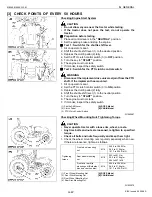
[3] CHECK POINTS OF EVERY 50 HOURS
Checking Engine Start System
CAUTION
• Do not allow anyone near the tractor while testing.
• If the tractor does not pass the test, do not operate the
tractor.
Q
Preparation before testing
1. Place all control levers in the
“NEUTRAL”
position.
2. Set the parking brake and stop the engine.
Q
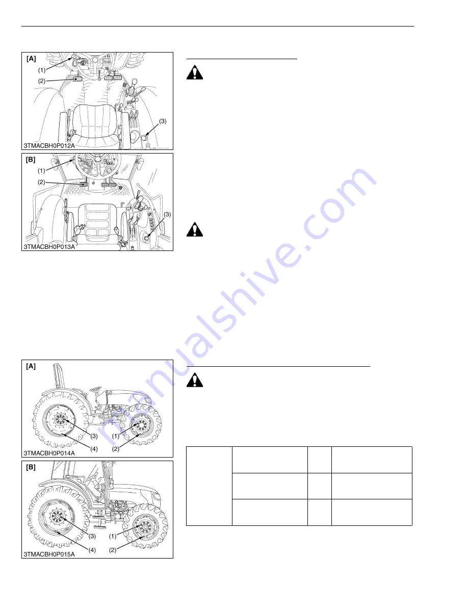
Test 1 : Switch for the shuttle shift lever.
1. Sit on operator’s seat.
2. Shift the shuttle shift lever (1) to the desired position.
3. Depress the clutch pedal (2) fully.
4. Set the PTO clutch control switch (3) to
OFF
position.
5. Turn the key to
“START”
position.
6. The engine must not crank.
7. If it cranks, inspect the safety switch.
Q
Test 2 : Switch for the PTO clutch control switch.
WARNING
• Disconnect the implement drive universal joint from the PTO
shaft, if the implement has mounted.
1. Sit on operator’s seat.
2. Set the PTO clutch control switch (3) to
ON
position.
3. Depress the clutch pedal (2) fully.
4. Shift the shuttle shift lever (1) to the neutral position.
5. Turn the key to
“START”
position.
6. The engine must not crank.
7. If it cranks, inspect the safety switch.
W1062967
Checking Wheel Mounting Nuts Tightening Torque
CAUTION
• Never operate tractor with a loose rim, wheel, or axle.
• Any time bolts and nuts are loosened, retighten to specified
torque.
• Check all bolts and nuts frequently and keep them tight.
1. Check the wheel mounting nuts regularly especially when new.
If there are loosened, tighten as follows.
W1023970
(1) Shuttle Shift Lever
(2) Clutch Pedal
(3) PTO Clutch Control Switch
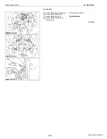
[A] ROPS Model
[B] CABIN Model
Tightening
torque
Front wheel mounting
nut
M16
259.9 to 304.0 N·m
26.5 to 31.0 kgf·m
191.7 to 224.2 lbf·ft
Rear wheel mounting
nut
M18
343 to 401 N·m
35.0 to 41.0 kgf·m
254 to 297 lbf·ft
Front and rear disc
mounting nut (Both steel
disc and cast iron disc)
M16
259.9 to 304.0 N·m
26.5 to 31.0 kgf·m
191.7 to 224.2 lbf·ft
(1) Front Wheel Mounting Nut
(2) Front Disc Mounting Nut
(3) Rear Wheel Mounting Nut
(4) Rear Disc Mounting Nut
[A] ROPS Model
[B] CABIN Model
KiSC issued 09, 2008 A
Содержание M9540
Страница 1: ...M8540 M9540 WORKSHOP MANUAL TRACTOR KiSC issued 09 2008 A...
Страница 8: ...6 M8540 M9540 WSM SAFETY INSTRUCTIONS KiSC issued 09 2008 A...
Страница 9: ...7 M8540 M9540 WSM SAFETY INSTRUCTIONS KiSC issued 09 2008 A...
Страница 10: ...8 M8540 M9540 WSM SAFETY INSTRUCTIONS Q CABIN Model KiSC issued 09 2008 A...
Страница 11: ...9 M8540 M9540 WSM SAFETY INSTRUCTIONS KiSC issued 09 2008 A...
Страница 12: ...10 M8540 M9540 WSM SAFETY INSTRUCTIONS KiSC issued 09 2008 A...
Страница 16: ...14 M8540 M9540 WSM DIMENSIONS DIMENSIONS ROPS Model KiSC issued 09 2008 A...
Страница 17: ...15 M8540 M9540 WSM DIMENSIONS CABIN Model KiSC issued 09 2008 A...
Страница 18: ...G GENERAL KiSC issued 09 2008 A...
Страница 103: ...1 ENGINE KiSC issued 09 2008 A...
Страница 203: ...2 CLUTCH KiSC issued 09 2008 A...
Страница 219: ...3 TRANSMISSION KiSC issued 09 2008 A...
Страница 322: ...4 REAR AXLE KiSC issued 09 2008 A...
Страница 323: ...CONTENTS MECHANISM 1 FEATURES 4 M1 KiSC issued 09 2008 A...
Страница 336: ...5 BRAKES KiSC issued 09 2008 A...
Страница 374: ...6 FRONT AXLE KiSC issued 09 2008 A...
Страница 375: ...CONTENTS MECHANISM 1 STRUCTURE 6 M1 1 FRONT AXLE 6 M1 2 LIMITED SLIP DIFFERENTIAL LSD 6 M2 KiSC issued 09 2008 A...
Страница 401: ...7 STEERING KiSC issued 09 2008 A...
Страница 402: ...CONTENTS MECHANISM 1 STEERING MECHANISM 7 M1 2 STEERING CYLINDER 7 M2 KiSC issued 09 2008 A...
Страница 420: ...8 HYDRAULIC SYSTEM KiSC issued 09 2008 A...
Страница 473: ...9 ELECTRICAL SYSTEM KiSC issued 09 2008 A...
Страница 554: ...10 CABIN KiSC issued 09 2008 A...


