1-S46
M8540, M9540, WSM
ENGINE
(Continued)
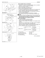
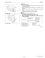
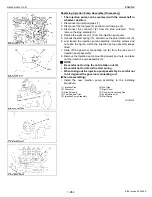
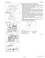
(Reassembling the fuel injection pump unit)
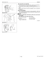
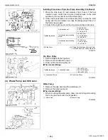
1. Place the piston of the 4th cylinder at the top dead center in the
compression stroke. Fix the flywheel with the flywheel stopper.
2. Set the timer 0
°
restoring jig (3) to the timer gear (2).
3. Place the timer gear (2) back into the gear case position. Make
sure of aligning the align marks of the timer gear and the idle gear
2.
4. Install the injection pump unit (1) to the timer gear (2).
NOTE
Q
• When installing the injection pump unit to the timer gear,
make sure that the key is fit in the keyway of timer gear.
5. Temporarily tighten the timer gear mounting nut by hand.
6. Fix the injection pump unit and tighten the timer gear mounting
nut to the specified torque.
7. Take off the fuel camshaft lock screws (4) and tighten the plugs
(5) for plugging.
8. Loose the injection pump unit mounting nuts (7) for aligning the
injection timing.
9. Moving the injection pump unit clockwise (viewed from gear case
side), align the injection timing marks (6) on the injection pump
unit and on the gear case.
10.Tighten the injection pump unit mounting nut (7) to the specified
torque.
11.Reconnect the lubricating oil pipe (8) and place the injection
pump unit support.
12.Remove the flywheel stopper.
13.Check the injection timing. (See the “Injection Timing”.)
14.If the injection timing is not within the specification, repeat (7) to
(12) again.
15.Remove the timer 0
°
restoring jig (3) from the timer gear (2).
16.Set the gear cover (9) and the timer lubricating pipe (10).
W1191026
Tightening torque
Timer gear mounting nut
74 to 83 N·m
7.5 to 8.5 kgf·m
55 to 61 lbf·ft
Injection pump unit
mounting nut
18 to 20 N·m
1.8 to 2.1 kgf·m
13 to 15 lbf·ft
(1) Injection Pump Unit
(2) Timer Gear
(3) Timer 0
°
restoring jig
(4) Fuel Camshaft Lock Screw
(Socket Set Screw Dog Point Type)
(5) Plug
(6) Align Mark
(7) Injection Pump Unit Mounting Nut
(8) Lubricating Oil Pipe
(9) Gear Cover
(10) Timer Lubricating Pipe
KiSC issued 09, 2008 A
Содержание M9540
Страница 1: ...M8540 M9540 WORKSHOP MANUAL TRACTOR KiSC issued 09 2008 A...
Страница 8: ...6 M8540 M9540 WSM SAFETY INSTRUCTIONS KiSC issued 09 2008 A...
Страница 9: ...7 M8540 M9540 WSM SAFETY INSTRUCTIONS KiSC issued 09 2008 A...
Страница 10: ...8 M8540 M9540 WSM SAFETY INSTRUCTIONS Q CABIN Model KiSC issued 09 2008 A...
Страница 11: ...9 M8540 M9540 WSM SAFETY INSTRUCTIONS KiSC issued 09 2008 A...
Страница 12: ...10 M8540 M9540 WSM SAFETY INSTRUCTIONS KiSC issued 09 2008 A...
Страница 16: ...14 M8540 M9540 WSM DIMENSIONS DIMENSIONS ROPS Model KiSC issued 09 2008 A...
Страница 17: ...15 M8540 M9540 WSM DIMENSIONS CABIN Model KiSC issued 09 2008 A...
Страница 18: ...G GENERAL KiSC issued 09 2008 A...
Страница 103: ...1 ENGINE KiSC issued 09 2008 A...
Страница 203: ...2 CLUTCH KiSC issued 09 2008 A...
Страница 219: ...3 TRANSMISSION KiSC issued 09 2008 A...
Страница 322: ...4 REAR AXLE KiSC issued 09 2008 A...
Страница 323: ...CONTENTS MECHANISM 1 FEATURES 4 M1 KiSC issued 09 2008 A...
Страница 336: ...5 BRAKES KiSC issued 09 2008 A...
Страница 374: ...6 FRONT AXLE KiSC issued 09 2008 A...
Страница 375: ...CONTENTS MECHANISM 1 STRUCTURE 6 M1 1 FRONT AXLE 6 M1 2 LIMITED SLIP DIFFERENTIAL LSD 6 M2 KiSC issued 09 2008 A...
Страница 401: ...7 STEERING KiSC issued 09 2008 A...
Страница 402: ...CONTENTS MECHANISM 1 STEERING MECHANISM 7 M1 2 STEERING CYLINDER 7 M2 KiSC issued 09 2008 A...
Страница 420: ...8 HYDRAULIC SYSTEM KiSC issued 09 2008 A...
Страница 473: ...9 ELECTRICAL SYSTEM KiSC issued 09 2008 A...
Страница 554: ...10 CABIN KiSC issued 09 2008 A...


