


1-S75
M8540, M9540, WSM
ENGINE
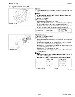
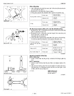
Connecting Rod Alignment
NOTE
Q
• Since the I.D. of the connecting rod small end bushing is the
basis of this check, check the bushing for wear beforehand.
1. Remove the piston pin in the connecting rod.
2. Install the piston pin in the connecting rod.
3. Install the connecting rod on the connecting rod alignment tool.
4. Put a gauge over the piston pin, and move it against the face
plate.
5. If the gauge does not fit squarely against the face plate, measure
the space between the pin of the gauge and the face plate.
6. If the measurement exceeds the allowable limit, replace the
connecting rod.
W1066581
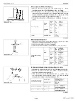
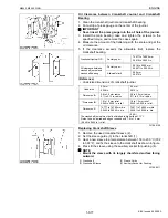
(4) Crankshaft
Crankshaft Side Clearance
1. Set a dial indicator with its tip on the end of the crankshaft.
2. Measure the side clearance by moving the crankshaft to the front
and rear.
3. If the measurement exceeds the allowable limit, replace the
thrust bearings.
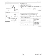
4. If the same size bearing is useless because of the crankshaft
journal wear, replace it with an oversize one referring to the table
and figure.
(Reference)
• Oversize dimensions of crankshaft journal.
W1066738
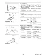
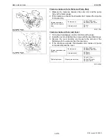
Crankshaft Alignment
1. Support the crankshaft with V block on the surface plate and set
a dial indicator with its tip on the intermediate journal at right
angle.
2. Rotate the crankshaft on the V block and get the misalignment
(half of the measurement).
3. If the misalignment exceeds the allowable limit, replace the
crankshaft.
W1067285
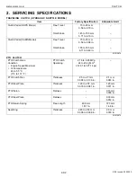
Connecting rod
alignment
Allowable limit
0.05 mm
0.0020 in.
Crankshaft side
clearance
Factory spec.
0.15 to 0.31 mm
0.0059 to 0.012 in.
Allowable limit
0.50 mm
0.020 in.
Oversize
0.2 mm
0.008 in.
0.4 mm
0.016 in.
Dimension
A
29.20 to 29.25 mm
1.1496 to 1.1515 in.
29.40 to 29.45 mm
1.1574 to 1.1594 in.
Dimension
B
169.1 to 169.15 mm
6.6575 to 6.6594 in.
169.2 to 169.25 mm
6.6614 to 6.6634 in.
Dimension
C
2.8 to 3.2 mm radius
0.1102 to 0.1260 in. radius
2.8 to 3.2 mm radius
0.1102 to 0.1260 in. radius
(0.8-S)
The crankshaft journal must be fine-finished to higher than
∇∇∇∇.
Crankshaft alignment
Allowable limit
0.02 mm
0.0008 in.
KiSC issued 09, 2008 A
Содержание M9540
Страница 1: ...M8540 M9540 WORKSHOP MANUAL TRACTOR KiSC issued 09 2008 A...
Страница 8: ...6 M8540 M9540 WSM SAFETY INSTRUCTIONS KiSC issued 09 2008 A...
Страница 9: ...7 M8540 M9540 WSM SAFETY INSTRUCTIONS KiSC issued 09 2008 A...
Страница 10: ...8 M8540 M9540 WSM SAFETY INSTRUCTIONS Q CABIN Model KiSC issued 09 2008 A...
Страница 11: ...9 M8540 M9540 WSM SAFETY INSTRUCTIONS KiSC issued 09 2008 A...
Страница 12: ...10 M8540 M9540 WSM SAFETY INSTRUCTIONS KiSC issued 09 2008 A...
Страница 16: ...14 M8540 M9540 WSM DIMENSIONS DIMENSIONS ROPS Model KiSC issued 09 2008 A...
Страница 17: ...15 M8540 M9540 WSM DIMENSIONS CABIN Model KiSC issued 09 2008 A...
Страница 18: ...G GENERAL KiSC issued 09 2008 A...
Страница 103: ...1 ENGINE KiSC issued 09 2008 A...
Страница 203: ...2 CLUTCH KiSC issued 09 2008 A...
Страница 219: ...3 TRANSMISSION KiSC issued 09 2008 A...
Страница 322: ...4 REAR AXLE KiSC issued 09 2008 A...
Страница 323: ...CONTENTS MECHANISM 1 FEATURES 4 M1 KiSC issued 09 2008 A...
Страница 336: ...5 BRAKES KiSC issued 09 2008 A...
Страница 374: ...6 FRONT AXLE KiSC issued 09 2008 A...
Страница 375: ...CONTENTS MECHANISM 1 STRUCTURE 6 M1 1 FRONT AXLE 6 M1 2 LIMITED SLIP DIFFERENTIAL LSD 6 M2 KiSC issued 09 2008 A...
Страница 401: ...7 STEERING KiSC issued 09 2008 A...
Страница 402: ...CONTENTS MECHANISM 1 STEERING MECHANISM 7 M1 2 STEERING CYLINDER 7 M2 KiSC issued 09 2008 A...
Страница 420: ...8 HYDRAULIC SYSTEM KiSC issued 09 2008 A...
Страница 473: ...9 ELECTRICAL SYSTEM KiSC issued 09 2008 A...
Страница 554: ...10 CABIN KiSC issued 09 2008 A...