42
Disassembly/Inspection and Service
KohlerEngines.com
18 690 01 Rev. F
1. Oil control ring assembly (bottom groove): Install
expander fi rst then bottom rail and top rail last. Make
sure ends of expander are not overlapped. Adjust
ring gaps.
2. Middle compression ring (center groove): Install
middle compression ring using a piston ring
expander tool. Make sure identifi cation mark is up or
colored dye stripe (if contained) is left of end gap.
Adjust ring gaps.
3. Top compression ring (top groove): Install top
compression ring using a piston ring expander tool.
Make sure identifi cation mark is up or colored dye
stripe (if contained) is left of end gap. Adjust ring
gaps.
Crankshaft Inspection and Service
Inspect gear teeth of crankshaft and ACR gear. If any
teeth are badly worn or chipped, or if some are missing,
replacement of crankshaft will be necessary.
Inspect crankshaft bearing surfaces for scoring,
grooving, etc. Measure running clearance between
crankshaft journals and their respective bearing bores.
Use an inside micrometer or telescoping gauge to
measure inside diameter of both bearing bores in vertical
and horizontal planes. Use an outside micrometer
to measure outside diameter of crankshaft main
bearing journals. Subtract journal diameters from their
respective bore diameters to get running clearances.
Check results against values in specifi cation tables. If
running clearances are within specifi cation, and there
is no evidence of scoring, grooving, etc., no further
reconditioning is necessary. If bearing surfaces are worn
or damaged, crankcase and/or closure plate will need to
be replaced.
Inspect crankshaft keyway. If worn or chipped,
replacement of crankshaft will be necessary.
Inspect crankpin for score marks or metallic pickup.
Slight score marks can be cleaned with crocus cloth
soaked in oil. If wear limits in Specifi cations are
exceeded, it will be necessary to replace crankshaft.
Remove Oil Sentry
™
System
1. Remove nut securing Oil Sentry
™
lead wire grommet
assembly to crankcase.
2. Pull grommet assembly from crankcase on inside.
3. Remove screws securing Oil Sentry
™
fl oat switch to
crankcase. Remove Oil Sentry
™
fl oat switch.
Remove Governor Assembly
NOTE: Mark location of all parts as governor assembly
is removed.
1. Remove hitch pin from governor cross shaft.
2. Remove governor cross shaft from inside crankcase.
3. Remove cup and washer from governor gear.
4. Using a suitable drift, drive governor gear shaft from
crankcase.
Inspection
Inspect governor gear teeth. Replace gear if it is worn,
chipped, or if any teeth are missing. Inspect governor
weights. They should move freely in governor gear.
Remove Crankcase and Closure Plate Seals and
Bearings
1. Remove oil seal from crankcase.
2. Using a suitable press, drive crankshaft bearing from
crankcase.
3. Remove oil seal from closure plate.
4. Using a suitable press, drive crankshaft bearing from
closure plate.
Crankcase
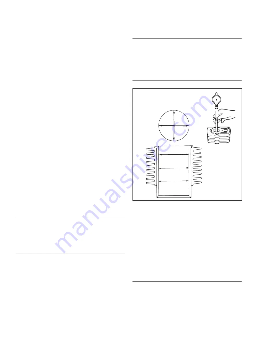
Cylinder Bore Details
Inspection and Service
Check all gasket surfaces to make sure they are free of
gasket fragments. Gasket surfaces must also be free of
deep scratches or nicks.
Check cylinder bore for scoring. In severe cases,
unburned fuel can cause scuffi ng and scoring of cylinder
wall. It washes necessary lubricating oils off piston and
cylinder wall. As raw fuel seeps down cylinder wall,
piston rings make metal-to-metal contact with wall.
Scoring of cylinder wall can also be caused by localized
hot spots resulting from blocked cooling fi ns or from
inadequate or contaminated lubrication.
If cylinder bore is badly scored, excessively worn,
tapered, or out-of-round, replacement is necessary. Use
an inside micrometer to determine amount of wear.
Breather Design
Breather system is designed to control amount of oil
in head area and still maintain necessary vacuum in
crankcase.
When pistons moves downward, crankcase gases are
pushed past reed through mesh fi lter into intake system.
Upward travel of pistons closes reed and creates a
low vacuum in lower crankcase. Any oil separated out
through fi lter drains back into crankcase.
Содержание Courage 3000 Series
Страница 53: ...53 18 690 01 Rev F KohlerEngines com...
Страница 54: ...54 KohlerEngines com 18 690 01 Rev F...
Страница 55: ...55 18 690 01 Rev F KohlerEngines com...
Страница 56: ...56 KohlerEngines com 18 690 01 Rev F 2019 by Kohler Co All rights reserved...


