TP-6252 2/08
42 Section 3 Scheduled Maintenance
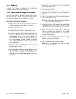
3.11 Battery
Consult the battery manufacturer’s instructions
regarding battery care and maintenance.
3.12 Generator Storage Procedure
Keep the craft afloat for generator operation during the
storage procedure. Follow the procedure below when
storing your generator set for 3 months or more.
Generator Set Storage Procedure
1. Start and run the generator set until it reaches
operating temperature or about 15 minutes.
2. Stop the generator set.
3. Change the oil and oil filter. See Section 3.5.3.
4. Close the seacock and remove the hose at the
seacock. Place the hose in a container having
approximately 3.7--7.5 L (1--2 U.S. gallons) of
coolant/antifreeze. Kohler Co. recommends using
an environmentally friendly potable antifreeze
such as Peak
R
RV/marine propylene glycol/water
mix or equivalent.
5. Disconnect the lead (#87) to the low seawater
pressure (LWP) switch.
6. With a suitable container at the exhaust outlet, run
the generator set until coolant discharges at the
exhaust outlet or until the coolant mixture is
depleted. Do not allow coolant mixture to flow into
waterways.
7. Reconnect the lead (#87) to the low seawater
pressure (LWP) switch.
8. Stop the generator set.
9. Connect a hose to the seacock. Leave the seacock
closed.
10. Check the coolant level of the heat exchanger and
add coolant if necessary.
Note:
Use antifreeze capable of withstanding the
lowest possible temperatures.
11. Clean the exterior of the generator set and spread
a light film of oil or silicon spray over any exposed
surfaces that may be subject to rust or corrosion.
12. Disconnect and remove the battery. Place the
battery in a warm, dry location for the storage
period. Recharge the battery once a month to
maintain a full charge.
13. Select a well-ventilated (not humid or dusty)
location to store the generator.
14. Cover the entire unit with a dust cover.
Note:
Run the generator set once a month
whenever possible.
Содержание 4.5EFOD
Страница 1: ...Marine Generator Sets Models 6EOD 4 5EFOD 8 32EOZD 6 5 27EFOZD TP 6252 2 08c Operation ...
Страница 8: ...TP 6252 2 08 8 Safety Precautions and Instructions Notes ...
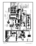
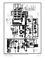
Страница 48: ...TP 6252 2 08 48 Section 5 Wiring Diagrams GM42202 E Figure 5 2 Wiring Diagram for Model 6EOD 4 5EFOD ...
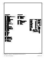
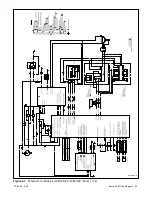
Страница 49: ...TP 6252 2 08 49 Section 5 Wiring Diagrams ADV7095A D Figure 5 3 Schematic for Model 6EOD 4 5EFOD Sheet 1 of 2 ...
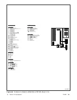
Страница 50: ...TP 6252 2 08 50 Section 5 Wiring Diagrams ADV7095B D Figure 5 4 Schematic for Model 6EOD 4 5EFOD Sheet 2 of 2 ...
Страница 51: ...TP 6252 2 08 51 Section 5 Wiring Diagrams GM50490 B Figure 5 5 Wiring Diagram for Model 9EOZD 7EFOZD ...
Страница 58: ...TP 6252 2 08 58 ...
Страница 59: ...TP 6252 2 08 59 ...

