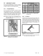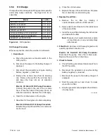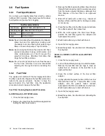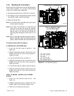
TP-6252 2/08
36 Section 3 Scheduled Maintenance
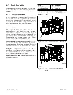
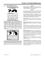
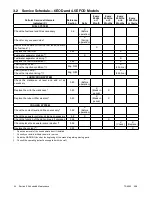
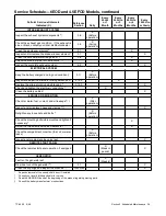
3.9 Cooling System
3.9.1 Closed Heat Exchanger
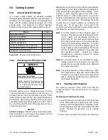
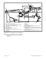
In a closed cooling system, the seawater circulates
through separate chambers within the heat exchanger or
manifold to cool the engine coolant. The seawater then
mixes with the engine exhaust and ejects out of the
exhaust outlet. See Figure 3-8 for coolant capacities
(include coolant recovery tank capacity of 0.24 L (8 oz.).
Model
L (Qts.)
6EOD and 4.5EFOD
2.0 (2.1)
8EOZD and 6.5EFOZD
3.9 (4.1)
9EOZD and 7EFOZD
2.5 (2.6)
10EOZD and 9EFOZD
2.5 (2.6)
13/14/15.5EOZD and 11/11.5/13EFOZD
4.4 (4.6)
20/23/24EOZD and 17/17.5/20EFOZD
6.0 (6.3)
28/32EOZD and 23/27EFOZD
7.6 (8.0)
Figure 3-8
Engine Coolant Capacities
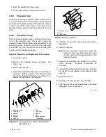
3.9.2 Checking and Filling Coolant
Hot coolant and steam.
Can cause severe injury or death.
Before removing the pressure cap,
stop the generator set and allow it to
cool. Then loosen the pressure cap
to relieve pressure.
WARNING
Allow the engine to cool. Release pressure from the
cooling system before removing the pressure cap. To
release pressure, cover the pressure cap with a thick
cloth and then slowly turn the cap counterclockwise to
the first stop. Remove the cap after pressure has been
completely released and the engine has cooled. Check
the coolant level at the tank if the generator set has a
coolant recovery tank.
NOTICE
Saltwater damage.
Saltwater quickly deteriorates metals.
Wipe up saltwater on and around the generator set and
remove salt deposits from metal surfaces.
Maintain the coolant level in the coolant recovery tank at
approximately 1/4 full. Before filling the cooling system,
close all petcocks and tighten all hose clamps. Use a
solution of 50% ethylene glycol and 50% clean,
softened water to inhibit rust/corrosion and prevent
freezing. Add additional coolant solution, as necessary,
to the coolant recovery tank. Periodically check the
coolant level on closed systems by removing the
pressure cap. Do not rely solely on the level in the
coolant recovery tank. Add fresh coolant until the level is
just below the overflow tube opening.
Note:
A coolant solution of 50% ethylene glycol is
required. This mix provides freezing protection to
--37
°
C (--34
°
F) and overheating protection to
129
°
C (265
°
F). A coolant solution with less than
50% ethylene glycol may not provide adequate
freezing and overheating protection. A coolant
solution with more than 50% ethylene glycol can
cause engine or component damage. Do not use
alcohol or methanol antifreeze or mix them with
the specified coolant.
Consult the engine
manufacturer’s operation manual for engine
coolant specifications.
Note:
Do not add coolant to an overheated engine.
Adding coolant to a hot engine can cause the
cylinder block or cylinder head to crack. Wait until
the engine has cooled.
Note:
Pay special attention to the coolant level. After
the coolant drains, allow time when refilling the
coolant for a complete refill of the engine water
jacket. Check the coolant level as prescribed in
the Prestart Checklist.
3.9.3 Flushing and Cleaning
For optimum protection, drain, flush, and refill the
cooling system at the interval listed in the service
schedule.
Flushing and Cleaning Procedure
1. Open the pressure cap and open petcocks located
at the heat exchanger, engine block, and cooling
system, and let the system drain completely. Some
models may have petcocks located behind the belt
guard. Remove the pressure cap to simplify
draining.
2. Drain, clean, and flush the coolant recovery tank.
Содержание 4.5EFOD
Страница 1: ...Marine Generator Sets Models 6EOD 4 5EFOD 8 32EOZD 6 5 27EFOZD TP 6252 2 08c Operation ...
Страница 8: ...TP 6252 2 08 8 Safety Precautions and Instructions Notes ...
Страница 48: ...TP 6252 2 08 48 Section 5 Wiring Diagrams GM42202 E Figure 5 2 Wiring Diagram for Model 6EOD 4 5EFOD ...
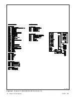
Страница 49: ...TP 6252 2 08 49 Section 5 Wiring Diagrams ADV7095A D Figure 5 3 Schematic for Model 6EOD 4 5EFOD Sheet 1 of 2 ...
Страница 50: ...TP 6252 2 08 50 Section 5 Wiring Diagrams ADV7095B D Figure 5 4 Schematic for Model 6EOD 4 5EFOD Sheet 2 of 2 ...
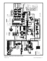
Страница 51: ...TP 6252 2 08 51 Section 5 Wiring Diagrams GM50490 B Figure 5 5 Wiring Diagram for Model 9EOZD 7EFOZD ...
Страница 58: ...TP 6252 2 08 58 ...
Страница 59: ...TP 6252 2 08 59 ...

