TP-6252 2/08
21
Section 2 Operation
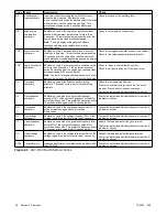
Code Fault
Description
Check
HB
High battery
voltage warning
Fault code is displayed if the engine starting battery
voltage rises above 16 VDC for a 12 VDC system or
above 30 VDC for a 24 VDC system for more than
2 seconds when the engine is not running. This fault
condition does not inhibit engine starting.
The fault condition clears when the battery voltage
returns to a voltage within the limits for more than
2 seconds.
Check the battery rating and condition.
LB
Low battery
voltage warning
Fault code is displayed if the engine starting battery
voltage falls below 9.5 VDC for a 12 VDC system or
below 16 VDC for a 24 VDC system for more than
2 seconds when the engine is not running. This fault
condition does not inhibit engine starting.
The fault condition clears when the battery voltage
returns to a voltage within the limits for more than
2 seconds.
Check the battery rating and condition.
Charge or replace the battery.
Figure 2-6
ADC 2100 Fault Warning Codes
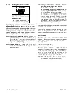
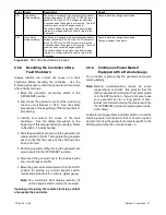
2.6.5 Resetting the Controller after a
Fault Shutdown
Always identify and correct the cause of a fault
shutdown before resetting the controller. Use the
following procedure to reset the generator set controller
after a fault shutdown.
1. Move the generator set master switch to the
OFF/RESET position.
2. Disconnect the generator set from the load using
the line circuit breaker or ATS. See the safety
precautions at the beginning of this manual before
proceeding.
3. Identify and correct the cause of the fault
shutdown. See the safety precautions at the
beginning of this manual before proceeding. Refer
to Section 4, Troubleshooting.
4. Start the generator set by moving the generator set
master switch to RUN. Test operate the generator
set to verify that the cause of the shutdown has
been corrected.
5. Shut the generator off by moving the generator set
master switch to the OFF/RESET position.
6. Reconnect the generator set to the load using the
line circuit breaker or ATS.
7. Move the generator set master switch to the AUTO
position for startup by remote transfer switch,
remote start/stop switch, or remote digital gauge.
Note:
The controller’s LED display remains off
until an engine start command is received.
Opening and closing the remote start/stop contact
also resets the controller.
2.6.6 Continuous Power Mode if
Equipped with a Remote Gauge
The controller is powered by the generator set engine
starting battery.
Note:
Remote communications require an active
(powered-up) controller. Be advised that the
ADC consumes 250 mA when the master switch
is in the AUTO position. If you do not plan to use
your generator set for a long period of time,
Kohler recommends moving the master switch to
the OFF/RESET position (complete power down,
0 mA draw).
A remote start signal (from a transfer switch or a remote
start/stop switch connected to P21 connector, leads 3
and 4) or moving the generator set master switch to the
RUN position turns the controller back on.
Содержание 4.5EFOD
Страница 1: ...Marine Generator Sets Models 6EOD 4 5EFOD 8 32EOZD 6 5 27EFOZD TP 6252 2 08c Operation ...
Страница 8: ...TP 6252 2 08 8 Safety Precautions and Instructions Notes ...
Страница 48: ...TP 6252 2 08 48 Section 5 Wiring Diagrams GM42202 E Figure 5 2 Wiring Diagram for Model 6EOD 4 5EFOD ...
Страница 49: ...TP 6252 2 08 49 Section 5 Wiring Diagrams ADV7095A D Figure 5 3 Schematic for Model 6EOD 4 5EFOD Sheet 1 of 2 ...
Страница 50: ...TP 6252 2 08 50 Section 5 Wiring Diagrams ADV7095B D Figure 5 4 Schematic for Model 6EOD 4 5EFOD Sheet 2 of 2 ...
Страница 51: ...TP 6252 2 08 51 Section 5 Wiring Diagrams GM50490 B Figure 5 5 Wiring Diagram for Model 9EOZD 7EFOZD ...
Страница 58: ...TP 6252 2 08 58 ...
Страница 59: ...TP 6252 2 08 59 ...

