TP-6252 2/08
Safety Precautions and Instructions 5
Safety Precautions and Instructions
IMPORTANT SAFETY INSTRUCTIONS.
Electromechanical
equipment,
including generator sets, transfer
switches,switchgear, andaccessories,
can cause bodily harm and pose
life-threatening
danger
when
improperly installed, operated, or
maintained. To prevent accidents be
aware of potential dangers and act
safely. Read and follow all safety
precautions and instructions. SAVE
THESE INSTRUCTIONS.
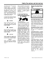
This manual has several types ofsafety
precautions and instructions: Danger,
Warning, Caution, and Notice.
DANGER
Danger indicates the presence of a
hazard that
will cause severe
personal injury, death
, or
substantial
property damage
.
WARNING
Warning indicates the presence of a
hazard that
can cause severe
personal injury, death,
or
substantial
property damage
.
CAUTION
Caution indicates the presence of a
hazard that
will
or
can cause minor
personal injury
or
property damage
.
NOTICE
Notice communicates installation,
operation, or maintenance information
that is safety related but not hazard
related.
Safety decals affixed to the equipment
in prominent places alert the operator
or service technician to potential
hazards and explain how to act safely.
The decals are shown throughout this
publication to improve operator
recognition.
Replace missing or
damaged decals.
Accidental Starting
Accidental starting.
Can cause severe injury or death.
Disconnect the battery cables before
working on the generator set.
Remove the negative (--) lead first
when disconnecting the battery.
Reconnect the negative (--) lead last
when reconnecting the battery.
WARNING
Disabling
the
generator
set.
Accidental starting can cause
severe injury or death.
Before
working on the generator set or
connected equipment, disable the
generator set as follows: (1) Move the
generator set master switch to the OFF
position. (2) Disconnect the power to
the battery charger. (3) Remove the
battery cables, negative (--) lead first.
Reconnect the negative (--) lead last
when reconnecting the battery. Follow
these precautions to prevent starting of
the generator set by an automatic
transfer switch, remote start/stop
switch, or engine start command from a
remote computer.
Engine Backfire/Flash
Fire
Fire.
Can cause severe injury or death.
Do not smoke or permit flames or
sparks near fuels or the fuel system.
WARNING
Servicing the fuel system. A flash
fire can cause severe injury ordeath.
Do not smoke or permit flames or
sparks near the fuel injection system,
fuel line, fuel filter, fuel pump, or other
potential sources of spilled fuels or fuel
vapors. Catch fuels in an approved
container when removing the fuel line
or fuel system.
Servicing the air cleaner. A sudden
backfire can cause severe injury or
death.
Do not operate the generator
set with the air cleaner/silencer
removed.
Combustible materials. A sudden
flash fire can cause severe injury or
death.
Do not smoke or permit flames
or sparks near the generator set. Keep
the compartment and the generator set
clean and free of debris to minimize the
risk of fire. Catch fuels in an approved
container. Wipe up spilled fuels and
engine oil.
Combustible materials. A fire can
cause severe injury or death.
Generator set engine fuels and fuel
vapors are flammable and explosive.
Handle these materials carefully to
minimize the risk of fire or explosion.
Equip the compartment or nearby area
with a fully charged fire extinguisher.
Select a fire extinguisher rated ABC or
BC for electrical fires or as
recommended by the local fire code or
an authorized agency.
Train all
personnel
on
fire
extinguisher
operation
and
fire
prevention
procedures.
Содержание 4.5EFOD
Страница 1: ...Marine Generator Sets Models 6EOD 4 5EFOD 8 32EOZD 6 5 27EFOZD TP 6252 2 08c Operation ...
Страница 8: ...TP 6252 2 08 8 Safety Precautions and Instructions Notes ...
Страница 48: ...TP 6252 2 08 48 Section 5 Wiring Diagrams GM42202 E Figure 5 2 Wiring Diagram for Model 6EOD 4 5EFOD ...
Страница 49: ...TP 6252 2 08 49 Section 5 Wiring Diagrams ADV7095A D Figure 5 3 Schematic for Model 6EOD 4 5EFOD Sheet 1 of 2 ...
Страница 50: ...TP 6252 2 08 50 Section 5 Wiring Diagrams ADV7095B D Figure 5 4 Schematic for Model 6EOD 4 5EFOD Sheet 2 of 2 ...
Страница 51: ...TP 6252 2 08 51 Section 5 Wiring Diagrams GM50490 B Figure 5 5 Wiring Diagram for Model 9EOZD 7EFOZD ...
Страница 58: ...TP 6252 2 08 58 ...
Страница 59: ...TP 6252 2 08 59 ...


